Method and Apparatus for Testing Breast Implants
a breast implant and mechanical technology, applied in the field of engineering mechanical properties, can solve the problems of difficult laboratory achievement, mechanical tests that have not exactly simulated the in vivo environment, and difficulty in laboratory achievement, and achieve the effect of describing the compressibility, firmness and shape stability of a breast implant, and the safety and durability of breast implants
- Summary
- Abstract
- Description
- Claims
- Application Information
AI Technical Summary
Benefits of technology
Problems solved by technology
Method used
Image
Examples
first invention embodiment
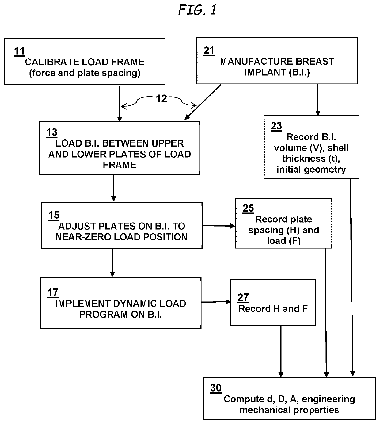
[0093]FIG. 4 illustrates load (F)-displacement (H) measurements for two breast implants. The load frame crosshead speed used for the testing of FIG. 4 was 25.4 cm / min, making the test run time for the data shown in FIG. 4 on the order of a few minutes. In FIG. 4, Breast implant #1 is a saline-filled dual-lumen breast implant in which the breast implant-platen area of contact is not lubricated, and Breast implant #2 is a single-lumen gel-filled breast implant in which the breast implant-platen area of contact is not lubricated.
[0094]These load-displacement measurements can be used to calculate all other breast implant geometric properties as well as engineering stresses, engineering strains and engineering moduli. FIG. 4 also illustrates that the load (F)-plate spacing (H) measurements may be taken manually or automatically by a data acquisition system integrated with the load frame apparatus. The manual (e.g., static) and automatic (e.g., dynamic) measurements on the same breast imp...
second invention embodiment
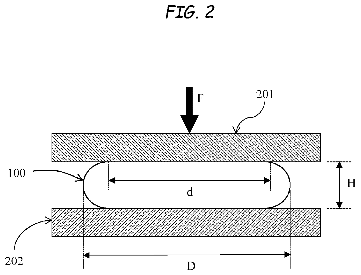
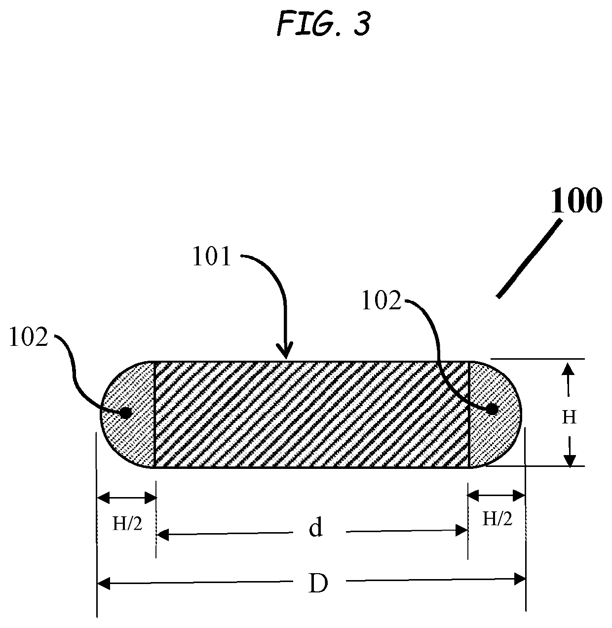
[0095]FIG. 5 also illustrates how this invention can be accurately applied to calculate the breast implant diameter D from Equation 4 as a function of load F using the plate spacing H data generated while implementing a dynamic load program. FIG. 5 also illustrates that a quasi-equilibrium assumption is valid, and that Equation 4 accurately represents the geometry of a compressed breast implant by comparing the manually measured breast implant diameter D to the computed breast implant diameter D. The manual, or static, measurements of D are taken at discrete loads, whereby the load frame is paused and manual measurements for D are taken. The automatic, or dynamic, values for D are determined from the dynamic data for plate spacing with a geometric model and quasi-equilibrium assumption as in Equation 4. In FIG. 5, Breast implant #1 is a gel-filled single-lumen breast implant in which the breast implant-platen area of contact is not lubricated, and Breast implant #2 is a another sing...
third invention embodiment
[0097]Using only the load (F)-displacement (H) data that is automatically sampled and recorded from a load frame apparatus while implementing a dynamic load program, various engineering strains can be calculated. FIG. 7 illustrates the diametric strain calculated from Equation 9 and dynamic load frame measurements, where the geometric property g is the breast implant diameter D, as a function of load F. The strain in FIG. 7 is expressed as a percentage, which is Equation 9 multiplied by 100%. Similarly, other strains for breast implant height H and breast implant surface area A can be computed. Given a breast implant's volume V (a constant), all strains can therefore be computed using the plate spacing H of the load frame apparatus through Equations 4 and 5. In FIG. 7, Breast implant #1 is a dual-lumen saline-filled breast implant in which the breast implant-platen area of contact is lubricated, Breast implant #2 is a gel-filled single-lumen breast implant in which the breast implan...
PUM
 Abstract
Description
Claims
Application Information
 - R&D
- Intellectual Property
- Life Sciences
- Materials
- Tech Scout
- Unparalleled Data Quality
- Higher Quality Content
- 60% Fewer Hallucinations
Browse by: Latest US Patents, China's latest patents, Technical Efficacy Thesaurus, Application Domain, Technology Topic, Popular Technical Reports.
© 2025 PatSnap. All rights reserved.Legal|Privacy policy|Modern Slavery Act Transparency Statement|Sitemap|About US| Contact US: help@patsnap.com


