
Center pillar manufacturing method

a manufacturing method and center pillar technology, applied in the field of center pillar manufacturing method of vehicles, can solve the problems of increasing the front-rear width of the center pillar of the vehicle, affecting the service life of the vehicle, so as to improve the resistance effect of the leg parts, prevent displacement, and suppress the effect of leg deformation

Pending Publication Date: 2020-11-12
HONDA MOTOR CO LTD
View PDF2 Cites 3 Cited by
  • Summary
  • Abstract
  • Description
  • Claims
  • Application Information

AI Technical Summary

Benefits of technology

The present invention provides a method for manufacturing a center pillar that is strong and lightweight against side impact loads. The method prevents displacement between two steel plates and uses a thick secondary steel plate as an U-shaped reinforcing member to improve resistance against a side impact load and prevent collapse deformation. The primary steel plate is press-molded into the W-shape while the secondary steel plate is press-molded into the U-shape, which reduces the size and weight of the secondary steel plate and allows for a complex W-shape.

Problems solved by technology

In this structure, however, leg portions that join the crest portions to the trough portion are not subjected to the quenching and are therefore prone to deformation without resisting a side impact load.
However, the increase in width dimensions of the primary steel plate leads to an increase in front-rear width of a center pillar of a vehicle, which is not desirable in light of potential deterioration of visibility.
On the other hand, the increase in plate thickness of the secondary steel plate causes an increase in weight and leads to reduction in fuel efficiency.

Method used


Image

  • Center pillar manufacturing method
  • Center pillar manufacturing method
  • Center pillar manufacturing method

Examples


Embodiment Construction

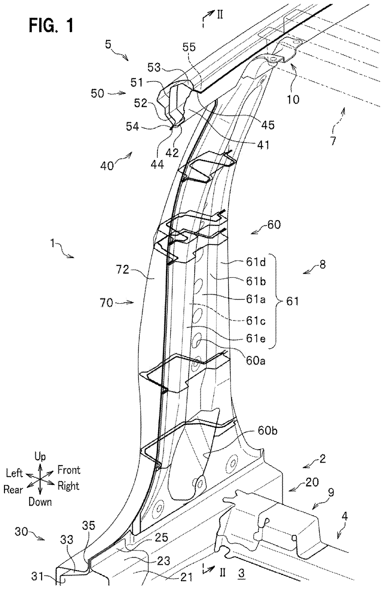
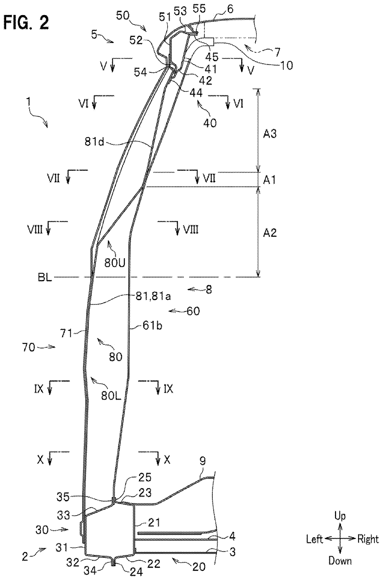
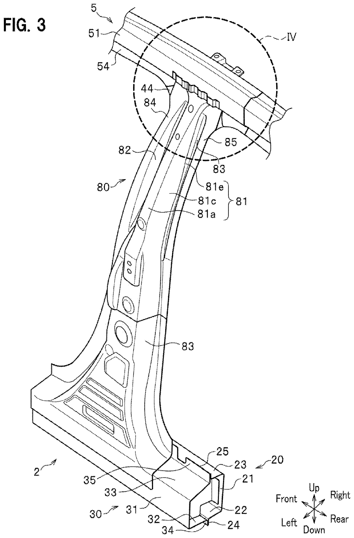
[0024]An embodiment of the present invention will be hereinafter described in detail with reference to the accompanying drawings as appropriate while focusing on an example in which a vehicle body side structure of the present invention is applied to a structure around a center pillar on a left side of a vehicle (such as an automobile). The same constituents will be denoted by the same reference signs and overlapping explanations thereof will be omitted. Terms indicating directions such as an up-down direction, a front-rear direction, and a right-left direction (a vehicle width direction) are based on the viewpoint of an occupant (a driver) of a vehicle.

[0025]

[0026]As shown in FIGS. 1 and 2, a vehicle body side structure 1 according to an embodiment of the present invention includes a side sill 2, a floor panel 3, a cross member 4, a roof side rail 5, a roof panel 6, a roof arch 7, a center pillar 8, a seat attachment bracket 9, and a roof arch connection bracket 10.

[0027]

[0028]The ...


PUM


Abstract

A center pillar manufacturing method includes: a first step of stacking a projected crest portion and a pair of projected joining wall portions of a primary steel plate on a secondary steel plate, and temporarily joining the primary steel plate to the secondary steel plate; a second step of forming a stiffener by subjecting the primary steel plate and the secondary steel plate to hot press; a third step of joining the stiffener to a center pillar outer member having an outer wall portion of the center pillar; and a fourth step of joining a pillar inner member having an inner wall portion of the center pillar to the pillar outer member after joining the stiffener.

Description

BACKGROUND OF THE INVENTION1. Field of the Invention[0001]The present invention relates to a CENTER PILLAR MANUFACTURING METHOD of a vehicle.2. Description of the Related Art[0002]A center pillar of a vehicle is designed to reduce its cross-section above a beltline in order to ensure visibility. Japanese Patent Application Publication No. 2004-314845 discloses a structure in which a portion of a center pillar above a beltline is reinforced by using a stiffener. The stiffener substantially takes on a W-shape in plan view at its portion above the beltline, thereby bringing crest portions and a trough portion thereof to be opposed to an inner wall portion and an outer wall portion of the center pillar. In the meantime, an outer end portion in a vehicle width direction of the stiffener is subjected to quenching so as to increase its hardness on a compression side in a bending action, thus suppressing bending deformation. In this structure, however, leg portions that join the crest porti...

Claims


Application Information

Patent Timeline
Patent Type & Authority Applications(United States)
IPC IPC(8): B62D25/04B62D65/02C21D9/46C21D1/18
CPCC21D9/46C21D1/18B62D25/04B62D65/02B62D29/007
Inventor SAKAI, HIROYUKI
Owner HONDA MOTOR CO LTD
Learn More