Transformer

a transformer and transformer technology, applied in transformers/inductance details, transformers/inductances magnetic cores, electrical apparatus, etc., can solve the problems of reducing the efficiency of the transformer from the primary coil to the secondary coil, increasing the entire height of the transformer, and difficult to cope with diversification of design (product tuning), so as to reduce the leakage of magnetic fields, increase the interface area, and improve efficiency

Active Publication Date: 2020-11-12
SOLUM CO LTD +1
View PDF4 Cites 1 Cited by
  • Summary
  • Abstract
  • Description
  • Claims
  • Application Information

AI Technical Summary

Benefits of technology

[0012]Therefore, the present invention has been made in view of the above problems, and the first object of the present invention is to provide a transformer including a primary substrate which is divided into an upper primary substrate and a lower primary substrate, thereby increasing an interface area between the upper and lower primary substrate and a secondary coil element which results in decreased magnetic field leakage and improved efficiency.
[0013]The second object of the present invention is to provide a transformer including upper and lower primary substrates and a secondary coil element which are alternatively arranged (in a zigzag pattern), thereby remarkably decreasing magnetic field leakage and thus improving efficiency from the upper and lower primary substrates to the secondary coil element.
[0014]The third object of the present invention is to provide a transformer including a secondary coil element which is interposed between two upper and lower primary substrates, thereby reducing occurrence of magnetic field leakage and thus improving efficiency from the primary substrates to the secondary coil element.

Problems solved by technology

However, the transformer of the related art has a problem in that since the upper and lower primary substrates are interposed between two secondary coil elements, magnetic field leakage occurs, and the efficiency of the transformer from the primary coils to the secondary coil is lowered.
Also, there is another problem in that since the secondary coil elements are separated in a vertical direction, the entire height of the transformer is increased.
Since the primary coils of the printed circuit board type are formed by patterning a certain circuit on the printed circuit board, a manufacturing period is extended, and thus it is inappropriate for a short delivery date.
Also, since the primary coils of the printed circuit board type are basically patterned on the printed circuit board, it is difficult to cope with diversification of design (product tuning).
In the case where the number of turns of the circuit patterns is increased, layers are increased, and thus the thickness of the printed circuit board becomes thick, which results in the increased volume of the primary coils.
Also, the price of the printed circuit board is raised to increase a cost of the product.

Method used


Image

  • Transformer
  • Transformer
  • Transformer

Examples


first embodiment

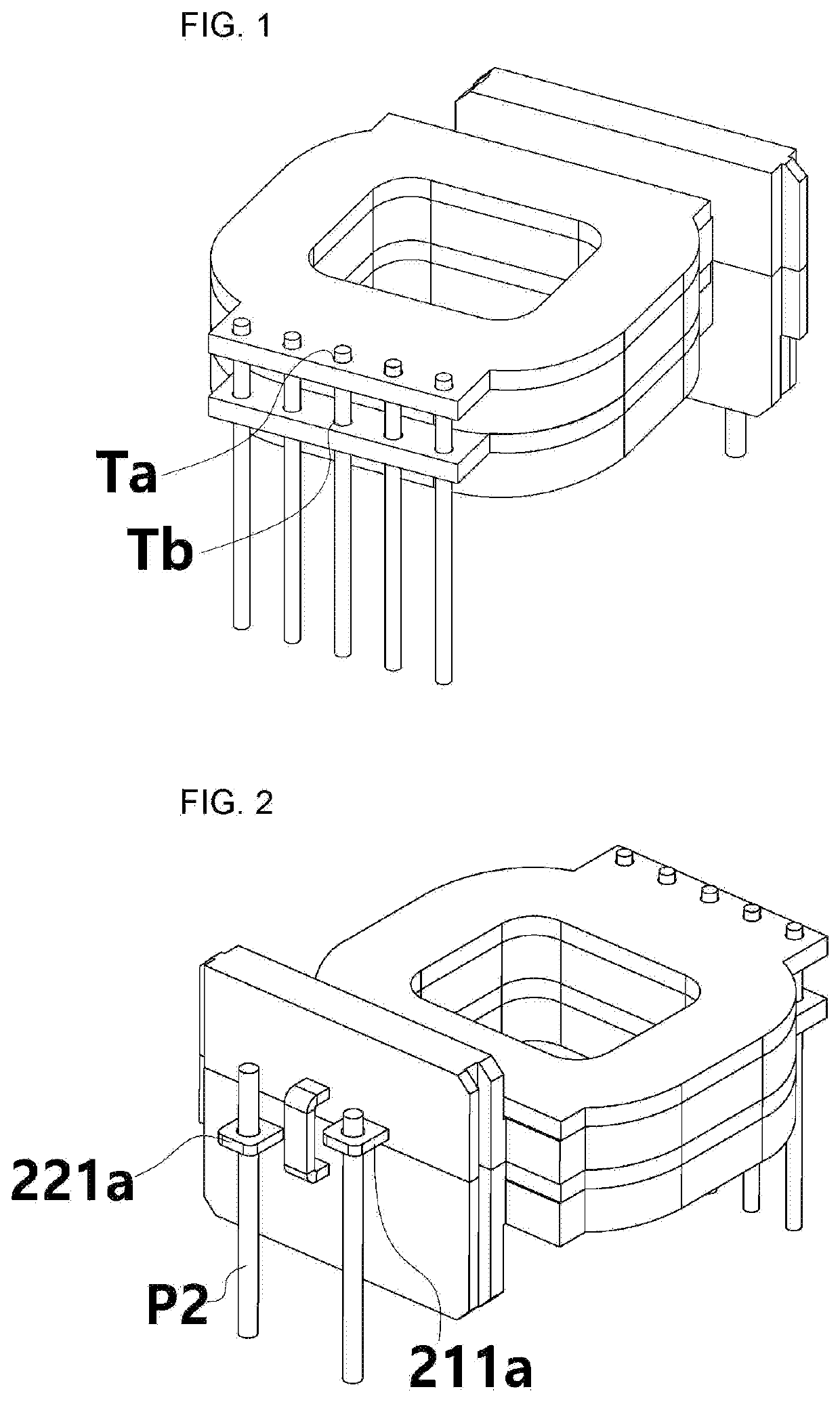
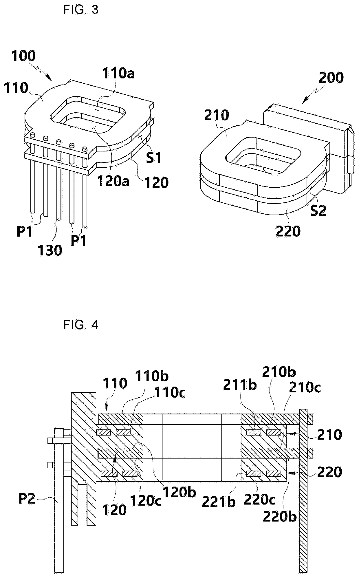
[0036]The transformer according to the present invention is characterized by including an upper primary substrate 110 which is formed by stacking a plurality of dielectric substrates, each substrate being provided with spiral conductive patterns; a lower secondary substrate 120 which is formed by stacking a plurality of dielectric substrates, each substrate being provided with spiral conductive patterns, in which the lower secondary substrate is positioned below the upper primary substrate110 in such a way that the lower secondary substrate comes into contact with the upper primary substrate 110 or is spaced apart from the upper primary substrate 110; and a secondary coil element 200 of a planar shape to produce an induced current by a current applied to the upper primary substrate 110 and the lower primary substrate 120.

[0037]The configuration including the upper primary substrate 110 and the lower primary substrate 120 is referred to as a primary substrate 100.

[0038]The upper prim...

second embodiment

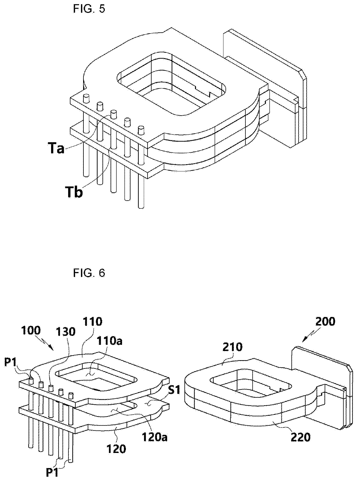
[0064]Now, the configuration and operation of a transformer according to the present invention will be described with reference to FIGS. 5 to 7.

[0065]As illustrated in FIGS. 5 to 7, the transformer according to the second embodiment of the present invention is characterized in that a secondary coil element is interposed between upper and lower primary substrates.

[0066]In the transformer according to the second embodiment of the present invention, a lower primary substrate 120 is positioned below an upper primary substrate 110, and is spaced apart from each other to form a receiving space S1 between the upper and lower primary substrates 110 and 120. A secondary coil element 200 is inserted in the receiving space S1 formed between the upper and lower primary substrates 110 and 120.

[0067]With the configuration in which the secondary coil element 200 is interposed between the upper and lower primary substrates 110 and 120, the magnetic field leakage is decreased to improve the efficien...


PUM

PropertyMeasurementUnit
conductiveaaaaaaaaaa
currentaaaaaaaaaa
shapeaaaaaaaaaa

Abstract

A transformer includes: an upper primary substrate (110) which is formed by stacking a plurality of dielectric substrates, each substrate being provided with spiral conductive patterns; a lower secondary substrate (120) which is formed by stacking a plurality of dielectric substrates, each substrate being provided with spiral conductive patterns, in which the lower secondary substrate is positioned below the upper primary substrate (110) in such a way that the lower secondary substrate comes into contact with the upper primary substrate (110) or is spaced apart from the upper primary substrate (110); and a secondary coil element (200) of a planar shape to produce an induced current by a current applied to the upper primary substrate (110) and the lower primary substrate (120).

Description

CROSS REFERENCE[0001]This application claims priority from Korean Patent Application No. 10-2019-0054099, filed on May 9, 2019, which is hereby incorporated by reference for all purposes as if fully set forth therein.BACKGROUND[0002]The present invention relates to a transformer, and more particularly, to a planar transformer for use in a charger or an adaptor.[0003]In general, a transformer includes a primary coil which services as an input terminal, and a secondary coil which services as an output terminal.[0004]One example of the transformers is disclosed by Korean Patent No. 10-1579427, published on Dec. 22, 2015, which proposes a compact transformer for use in a charger for a mobile phone.[0005]The transformer of the related art includes upper and lower primary substrates of a printed circuit board type, the upper and lower primary substrates being manufactured by patterning a conductive material on dielectric surfaces thereof.[0006]The upper and lower primary substrates of the...

Claims


Application Information

Patent Timeline
Patent Type & Authority Applications(United States)
IPC IPC(8): H01F27/28H01F27/29H01F27/32H01F27/30
CPCH01F2027/2809H01F27/32H01F27/24H01F27/29H01F27/2804H01F27/306H01F27/327H01F27/2852H01F2027/065H01F2027/297H01F27/027H01F30/06H01F27/346
Inventor KIM, EUN SIKLEE, JUN KYUKWON, CHANGYONGRYU, DONG-KYUNJI, SANG-KEUNHAN, TAEKSOOLEE, JUNG SOO
Owner SOLUM CO LTD
Why Eureka
Try Eureka