System and method for purging a fuel manifold of a gas turbine engine using a flow divider assembly

a gas turbine engine and flow divider technology, which is applied in the direction of turbine/propulsion fuel valves, machines/engines, lighting and heating apparatus, etc., can solve the problems of limiting the fuel efficiency gain and the amount of time required to restart the engin

Active Publication Date: 2020-11-19
PRATT & WHITNEY CANADA CORP
View PDF0 Cites 88 Cited by
  • Summary
  • Abstract
  • Description
  • Claims
  • Application Information

AI Technical Summary

Problems solved by technology

However, once a turboshaft engine is stopped, there is an amount of time required to restart the engine and have the engine running at a sufficient output power lev

Method used


Image

  • System and method for purging a fuel manifold of a gas turbine engine using a flow divider assembly
  • System and method for purging a fuel manifold of a gas turbine engine using a flow divider assembly
  • System and method for purging a fuel manifold of a gas turbine engine using a flow divider assembly

Examples


Embodiment Construction

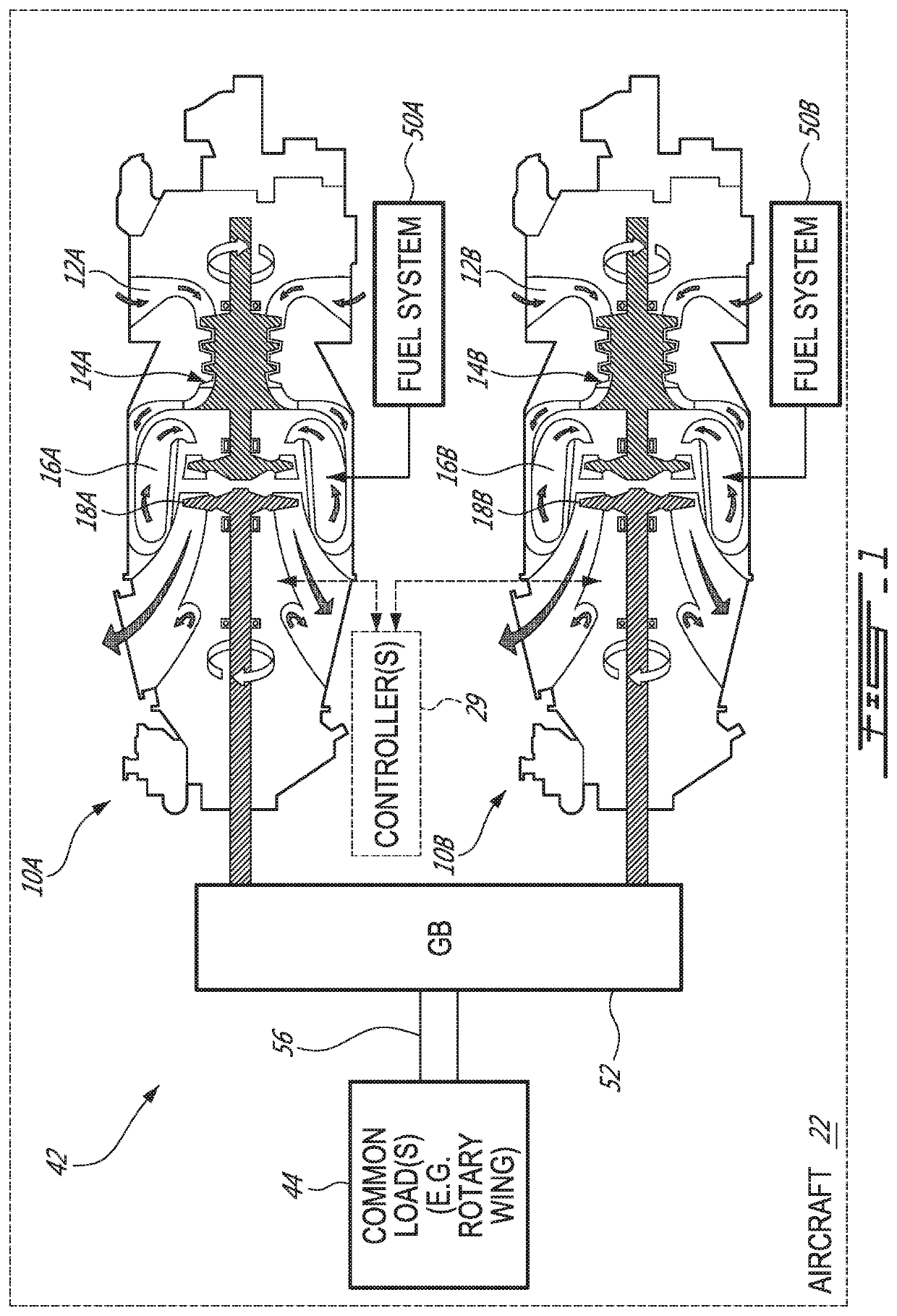
[0049]FIG. 1 schematically illustrates an exemplary multi-engine (e.g., twin-pack) power plant 42 that may be used for an aircraft 22, which may be a rotorcraft such as a helicopter. The multi-engine power plant 42 may include two or more GTEs 10A, 10B. The first gas turbine engine 10A is referred hereinafter as “FGTE 10A” and the second gas turbine engine 10B is referred hereinafter as “SGTE 10B”. In some instances FTGE 10A and / or SGTE 10B may be referred to generically as GTE 10 or GTEs 10A, 10B. In the case of a helicopter application, these GTEs 10A, 10B may be turboshaft engines. However, it is understood that methods, systems and components disclosed herein are applicable to other types of aircraft engines such as turbofans and turboprops for example.

[0050]FIG. 1 shows axial cross-section views of two exemplary GTEs 10A, 10B of the turboshaft type. Each of the GTEs 10A, 10B may comprise, in serial flow communication, respectively, air intake 12A, 12B through which ambient air ...


PUM


Abstract

Methods and systems of operating a gas turbine engine in a low-power condition are provided. In one embodiment, the method includes supplying fuel to the combustor by supplying fuel to the first fuel manifold via a first flow divider valve and supplying fuel to the second fuel manifold via a second flow divider valve. While supplying fuel to the combustor by supplying fuel to the first fuel manifold, the method includes stopping supplying fuel to the second fuel manifold and supplying pressurized gas to the second fuel manifold via the second flow divider valve to flush fuel in the second fuel manifold into the combustor and hinder coking in the second fuel manifold and associated nozzles.

Description

CROSS REFERENCE TO RELATED APPLICATIONS AND CLAIM OF PRIORITY[0001]The present application claims priority to: U.S. provisional patent application No. 62 / 848,187 filed on May 15, 2019 and incorporated herein by reference; U.S. provisional patent application No. 62 / 848,196 filed on May 15, 2019 and incorporated herein by reference; U.S. provisional patent application No. 62 / 848,223 filed on May 15, 2019 and incorporated herein by reference; U.S. provisional patent application No. 62 / 850,809 filed on May 21, 2019 and incorporated herein by reference; U.S. provisional patent application No. 62 / 848,231 filed on May 15, 2019 and incorporated herein by reference; and to U.S. provisional patent application No. 62 / 849,428 filed on May 17, 2019 and incorporated herein by reference.TECHNICAL FIELD[0002]The disclosure relates generally to gas turbine engines, and more particularly to the operation of gas turbine engines at low power conditions.BACKGROUND OF THE ART[0003]Twin-engine helicopters...

Claims


Application Information

Patent Timeline
IPC IPC(8): F02C7/30F02C6/00F02C6/16F02C9/42F02C7/22F02C7/236
CPCF02C6/00F02C6/16F02C9/42F02C7/222F02C7/236F02C7/30F02C7/232F02C7/228F05D2260/602F05D2220/329Y02E60/16F23D2209/30F23K2300/203
Inventor SAINTIGNAN, CÉDRICCIRTWILL, JOSEPH DANIEL MAXIMMCCALDON, KIANTREMBLAY, MARC-ANDRÉWADDLETON, DAVIDBROCCOLINI, IGNAZIOTARLING, STEPHEN
Owner PRATT & WHITNEY CANADA CORP
Why Eureka
Try Eureka