Method and apparatus for isothermal cooling

a technology of isothermal cooling and cooling apparatus, which is applied in the field of cooling and refrigeration, can solve the problems of poor isothermality and low performance of system evaporators, difficult to achieve isothermal heat rejection at a specified temperature with multiple evaporator channels and evaporators, and general unsatisfactory distribution of liquid flow

Active Publication Date: 2020-11-19
ROLLS ROYCE NORTH AMERICAN TECH
View PDF0 Cites 20 Cited by
  • Summary
  • Abstract
  • Description
  • Claims
  • Application Information

AI Technical Summary

Benefits of technology

[0010]According to one aspect of the technology described herein, a cooling apparatus includes: a first fluid flowpath including the following elements, in downstream flow sequence: a separator vessel; a subcooler having a first side in fluid communication with the first fluid flowpath and a second side configured to be disposed in thermal communication with a cold sink; a flow control valve; a primary evaporator assembly including at least one primary evaporator configured to be disposed in thermal communication with a primary heat load; and a pressure regulator operable to maintain a refrigerant saturation pressure within the primary evaporator at a predetermined set point.
[0011]According to another aspect of the technology described herein, a refrigeration apparatus includes: a first fluid flowpath including, in downstream flow sequence: a compressor having an inlet and an outlet; a cooler in fluid communication with the outlet of the compressor; a cooler flow restrictor; a separator vessel; a subcooler having a first side connected in fluid communication with the first fluid flowpath and a second side configured to be disposed in thermal communication with a cold sink; a flow control valve connected in fluid communication with the subcooler; a primary evaporator assembly including at least one primary evaporator configured to be disposed in thermal communication with a primary heat load; and a pressure regulator operable to maintain saturation pressure within the primary evaporator at a predetermined set point, wherein an outlet of the pressure regulator is in fluid communication with the inlet of the compressor.

Problems solved by technology

In the prior art, isothermal heat rejection at a specified temperature with multiple evaporator channels and evaporators has been difficult to achieve.
Most industry standard methods distribute liquid poorly at inlets to parallel evaporator channels and allow flow to exit beyond stable evaporation vapor quality, which produces poor isothermality and low performance at system evaporators.
Distribution of liquid flow is generally unsatisfactory and distribution amongst excessive numbers of channels (as in microchannel evaporators) becomes unwieldy.
Poor distribution of two-phase distributors results in channels with excess liquid and channels with too little liquid.
The channels with less liquid will not cool sufficiently and the channels with more liquid may over-cool.
Any pressure drop from the flash gas tank liquid outlet to evaporator(s) inlet(s) and then to each channel will cause formation of vapor and thereby increase maldistribution causing sub-optimal evaporator performance and less than ideal isothermality.
These systems generally require substantial liquid head at the inlet to each pump to avoid cavitation at pump impellers, which can generate vapor and cause premature failure of pumps.
Also, it can be difficult to control liquid conditions at the pump inlet of two-phase pumped loops and overly subcooled flow is common with low heat duty conditions.
Excessive subcool at evaporator inlets will produce varying temperatures and non-optimal evaporator performance.
The heat exchanger interface between two phase pumped loops and vapor compression systems can be excessively complex to maintain liquid condensate without excessive subcool.

Method used


Image

  • Method and apparatus for isothermal cooling
  • Method and apparatus for isothermal cooling
  • Method and apparatus for isothermal cooling

Examples


Embodiment Construction

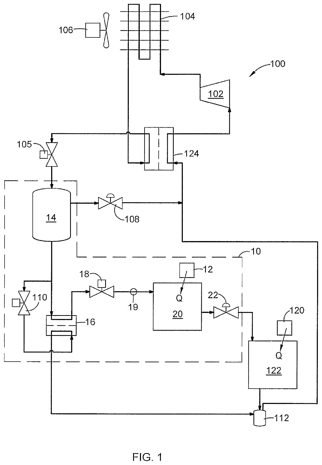
[0018]Referring to the drawings wherein identical reference numerals denote the same elements throughout the various views, FIG. 1 depicts an exemplary cooling apparatus 10 (bounded by a dashed line). The cooling apparatus 10 is operable to remove heat from at least one heat load. As used herein the term “heat load” refers to any device, system, or item of equipment which generates heat that needs to be removed. In particular, the heat load may be an isothermal heat load, meaning that heat must be removed at a constant, predetermined temperature for proper functioning of the equipment. In FIG. 1, a primary heat load 12, which is an isothermal heat load, is depicted schematically.

[0019]The cooling apparatus 10 fundamentally operates by providing a low-temperature liquid refrigerant to an evaporator which is thermally coupled to the primary heat load 12. Boiling of the refrigerant within the evaporator carries away heat energy. As will be explained in more detail below, the cooling ap...


PUM


Abstract

A cooling apparatus includes: a first fluid flowpath including the following elements, in downstream flow sequence: a separator vessel; a subcooler having a first side in fluid communication with the first fluid flowpath and a second side configured to be disposed in thermal communication with a cold sink; a flow control valve; a primary evaporator assembly including at least one primary evaporator configured to be disposed in thermal communication with a primary heat load; and a pressure regulator operable to maintain a refrigerant saturation pressure within the primary evaporator at a predetermined set point.

Description

BACKGROUND OF THE INVENTION[0001]This invention relates generally to cooling and refrigeration, and more particularly relates to isothermal cooling apparatus and processes.[0002]It is well-known to cool equipment, buildings, and vehicles with two-phase cooling or refrigeration apparatus. In some applications, it is desirable to reject heat at a specified temperature (i.e., isothermal heat rejection).[0003]In the prior art, isothermal heat rejection at a specified temperature with multiple evaporator channels and evaporators has been difficult to achieve. Most industry standard methods distribute liquid poorly at inlets to parallel evaporator channels and allow flow to exit beyond stable evaporation vapor quality, which produces poor isothermality and low performance at system evaporators. Other industry standard methods require excessive space and additional rotating equipment to provide ideal conditions at system evaporators.[0004]Direct expansion systems often use two-phase distri...

Claims


Application Information

Patent Timeline
Patent Type & Authority Applications(United States)
IPC IPC(8): F25B6/00F25B41/04F25B40/02
CPCF25B6/00F25B40/02F25B41/04F25B2400/13F25B5/04F25B40/00F25B2600/2509F25B2400/23F25B41/20
Inventor JANSEN, EUGENE CHARLES
Owner ROLLS ROYCE NORTH AMERICAN TECH
Why Eureka
Try Eureka