Unlock instant, AI-driven research and patent intelligence for your innovation.

Method and apparatus for electromagnetic signal waveguides

Inactive Publication Date: 2020-11-19
ALCATEL LUCENT SHANGHAI BELL CO LTD
View PDF0 Cites 0 Cited by
  • Summary
  • Abstract
  • Description
  • Claims
  • Application Information

AI Technical Summary

Benefits of technology

The invention provides a method for creating a waveguide substrate with two waveguide cavities and a recess on a side of another waveguide substrate element, which are joined together to form a continuous waveguide. The method includes milling the waveguide cavities and recess, as well as assembling the substrate elements together. The invention also provides an apparatus and a radio system using the waveguide substrate. The technical effects include improved signal transmission and reduced signal loss.

Problems solved by technology

The welding, brazing or arranging of a gasket on such a complex contour is expensive, and may introduce weak points when the soldering has different dilatation values than the rest of the waveguide and the temperature varies.
The welding may also be more susceptible to oxidization so that electromagnetic energy may eventually be lost when the sealing becomes incomplete, and the two blocks may even end up falling apart.

Method used


Image

  • Method and apparatus for electromagnetic signal waveguides
  • Method and apparatus for electromagnetic signal waveguides
  • Method and apparatus for electromagnetic signal waveguides

Examples


Embodiment Construction

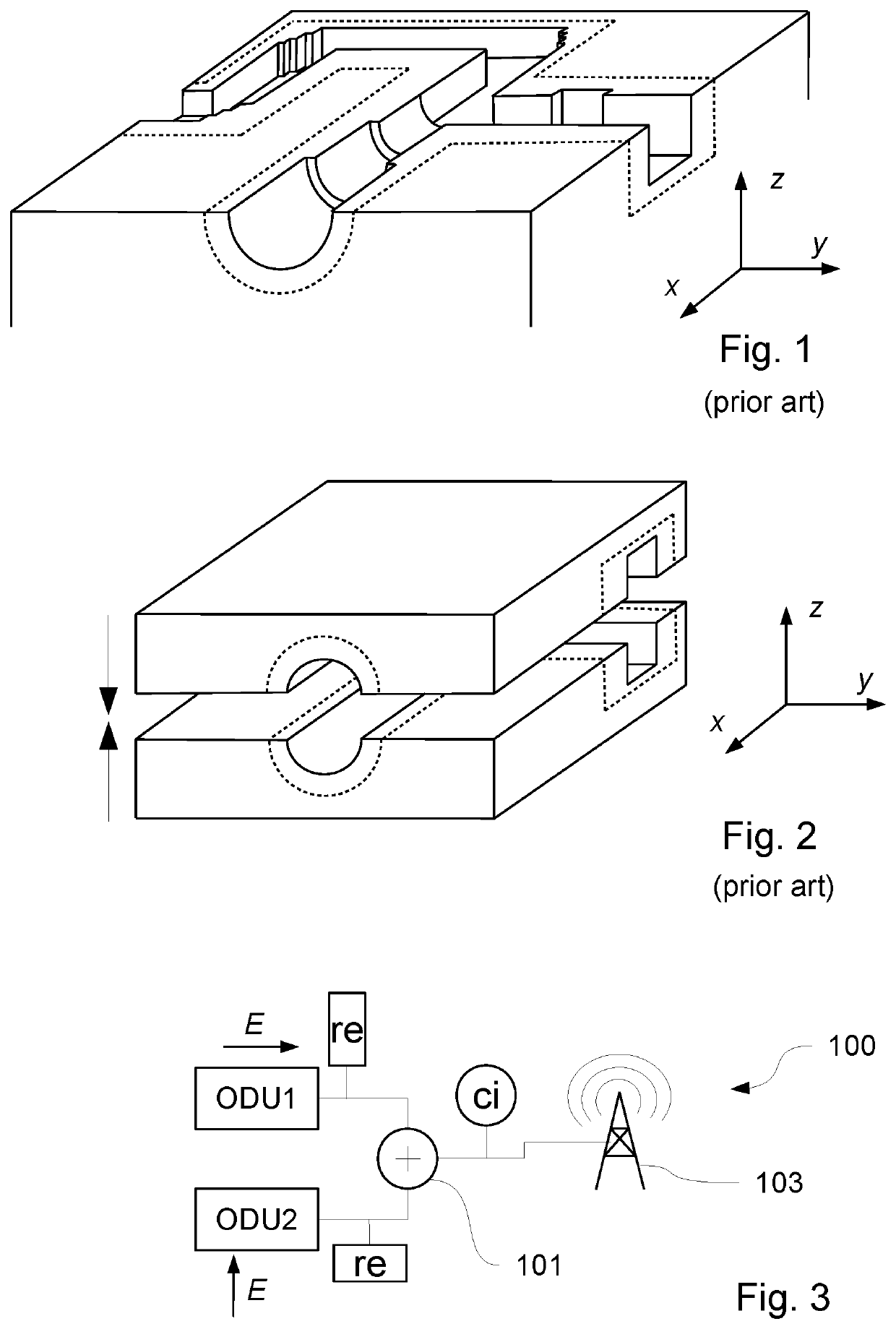
[0053]In an example embodiment, FIG. 3 shows a schematic representation of a radio system 100 comprising an orthomode transducer (OMT) 101, the radio system 100 being configured as an outdoor transmitter. Such radio systems comprising orthomode transducers 101 are used in 3G to 5G wireless networks to transmit data from one antenna to another antenna in the network, and thus forward data from cell to cell at network level. Other possible uses may include radar imaging, and network communication other than 3G or 4G cell-to-cell. In some, but not necessarily all, embodiments the radio system 100 may be configured as an indoor transmitter, an indoor receiver, an indoor transceiver, an outdoor transceiver or an outdoor receiver dependent on how the radio system is configured to be used.

[0054]In the example embodiment, the radio system 100 is configured to transmit RF microwave signals via an antenna 103 in an uplink direction to another antenna (not illustrated in FIG. 3). The OMT 101 c...


PUM


Abstract

The invention relates to a method comprising: ° milling of a first waveguide substrate element (1a) to provide two waveguide cavities (3, 5a) with respectively a first and a second port (3re, 5re) on a common side of the first substrate element (1a), ° milling of a recess (5b) on a side of a second waveguide substrate element (1b), ° assembling the first and second substrate elements (1a, 1b) so that the waveguide cavities (3, 5a) and the recess (5b) form a continuous waveguide.

Description

TECHNOLOGICAL FIELD[0001]The present invention concerns an orthomode transducer waveguide assembly, in particular for microwave frequencies, and for use in radio frequency communication systems.TECHNOLOGICAL BACKGROUND[0002]Waveguides, in particular microwave waveguides, are made using tubular segments of constant or near-constant transverse sections. The tubular segments are for example pipes made of metallic material at least on the inner surface of the walls (e.g. metal sheet on plastic walls). The skin effect and geometric properties of the waveguide then ensure that waves propagate along a longitudinal axis of the tubular segment, divided into stable electrical and magnetic propagation modes which are individual solutions to the linear propagation equation.[0003]The tubular segments are connected to each-other using flanges, angle bends and articulated connectors, resulting in waveguide assemblies combining different waveguide segments, each with particular functions (combiners...

Claims


Application Information

Patent Timeline
IPC IPC(8): H01P3/12H01P1/161H01P11/00H04B1/02H04B7/10
CPCH01P11/002H01P1/161H04B7/10H01P3/121H04B1/02
Inventor LE BAYON, ARMELTUAU, DENIS
Owner ALCATEL LUCENT SHANGHAI BELL CO LTD
Features
  • R&D
  • Intellectual Property
  • Life Sciences
  • Materials
  • Tech Scout
  • Unparalleled Data Quality
  • Higher Quality Content
  • 60% Fewer Hallucinations
Learn More