


Quick Research
Generate reliable direction feasibility study reports for your R&D in just a few steps.

Technical Q&A
Discover and master advanced knowledge NOW. Basics, ideas, possibilities, all at once.

Find Solutions
As an expert in R&D theories, this can generate solutions to your technical problems instantly.

Evaluate Feasibility
Analyze your overall solution with one click, know your potential R&D risks in advance.

Monitor Landscape
Get weekly tech updates, stay abreast of the latest tech innovations and key insights.
Position detection device
- Summary
- Abstract
- Description
- Claims
- Application Information
AI Technical Summary
Benefits of technology
Problems solved by technology
Method used
Image

Examples
first embodiment
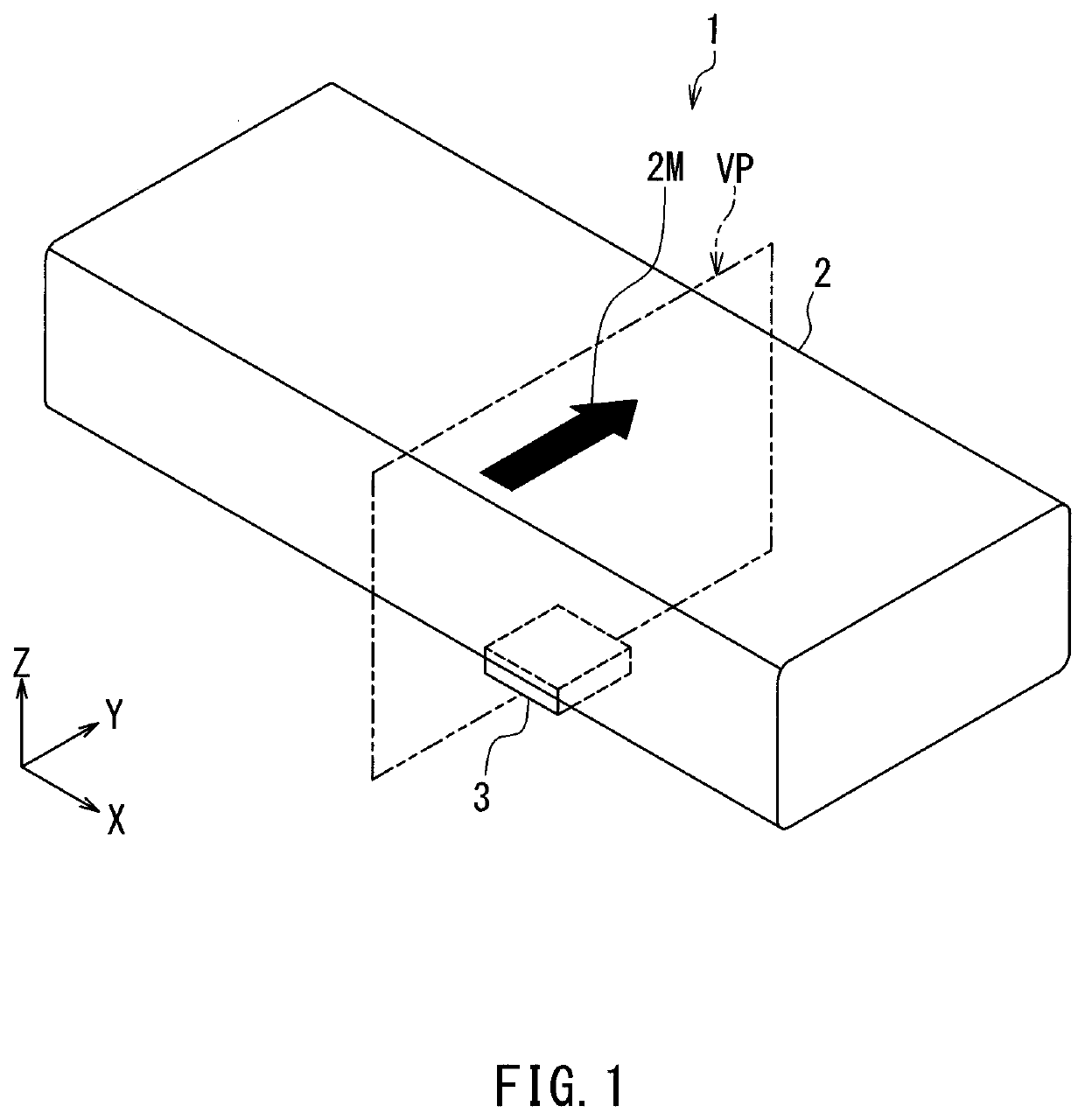
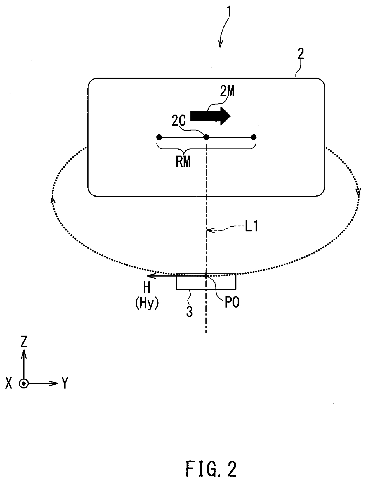
[0052]Preferred embodiments of the present invention will now be described in detail with reference to the drawings. Initially, a position detection device according to a first embodiment of the invention will be outlined with reference to FIGS. 1 and 2. As shown in FIGS. 1 and 2, a position detection device 1 according to the present embodiment includes a magnetic field generator 2 that generates a magnetic field to be detected and a magnetic sensor 3. The magnetic sensor 3 detects the magnetic field to be detected and generates a detection value Os corresponding to a relative position of the magnetic field generator 2 with respect to the magnetic sensor 3. In particular, in the present embodiment, the magnetic field generator 2 is a magnet. The magnet will hereinafter be also denoted by the reference numeral 2. A description of the magnet 2 applies to the magnetic field generator 2 as well.
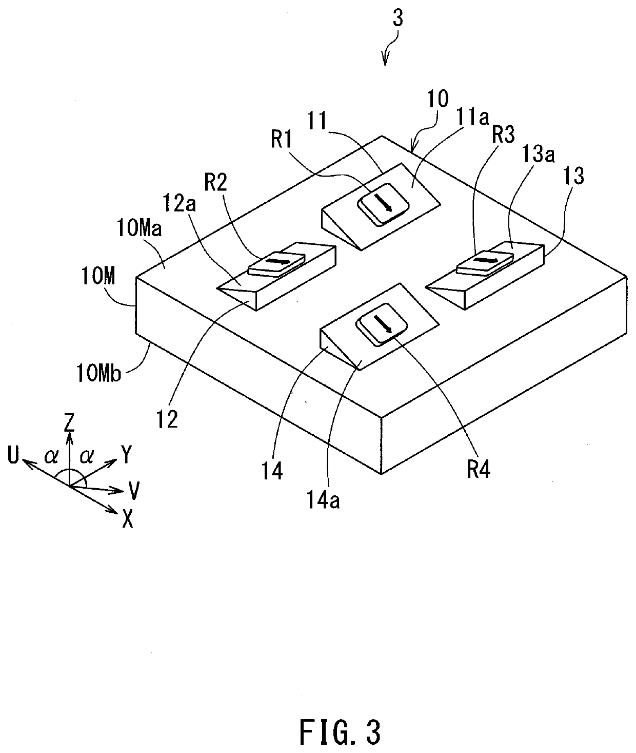
[0053]As will be described in detail later, the magnetic sensor 3 includes at least one magn...
second embodiment
[0132]A second embodiment of the invention will now be described. FIG. 15 is a perspective view of a position detection device 1 according to the present embodiment. FIG. 16 is a sectional view of the position detection device 1 according to the present embodiment. Differences of the position detection device 1 according to the present embodiment from the position detection device 1 according to the first embodiment will be described below. The position detection device 1 according to the present embodiment includes a magnetic field generator 62 instead of the magnetic field generator 2 of the first embodiment. In particular, in the present embodiment, the magnetic field generator 62 is a magnet. The magnet will hereinafter be also denoted by the reference numeral 62. A description of the magnet 62 applies to the magnetic field generator 62 as well.
[0133]The magnet 62 lies above the magnetic sensor 3. Like the first embodiment, the magnet 62 is magnetized in a direction parallel to ...
third embodiment
[0143]A third embodiment of the invention will now be described. FIG. 17 is a perspective view of a position detection device 1 according to the present embodiment. FIG. 18 is a sectional view of the position detection device 1 according to the present embodiment. Differences of the position detection device 1 according to the present embodiment from the position detection device 1 according to the first embodiment will be described below.
[0144]The position detection device 1 according to the present embodiment differs from the position detection device 1 according to the first embodiment in the range of movement RM of the magnet 2. The range of movement RM in the present embodiment is represented by a segment parallel to the Z direction. The range of movement RM lies in the vertical plane VP illustrated in FIG. 17. The vertical plane VP is a YZ plane. FIG. 18 shows a cross section taken along the vertical plane VP.
[0145]As shown in FIG. 18, in the present embodiment, the position r...
PUM
 Abstract
Description
Claims
Application Information
 - R&D Engineer
- R&D Manager
- IP Professional
- Industry Leading Data Capabilities
- Powerful AI technology
- Patent DNA Extraction
Browse by: Latest US Patents, China's latest patents, Technical Efficacy Thesaurus, Application Domain, Technology Topic, Popular Technical Reports.
© 2024 PatSnap. All rights reserved.Legal|Privacy policy|Modern Slavery Act Transparency Statement|Sitemap|About US| Contact US: help@patsnap.com