Wideband antenna device

Active Publication Date: 2020-12-10
JOYMAX ELECTRONICS CO LTD
View PDF0 Cites 2 Cited by
  • Summary
  • Abstract
  • Description
  • Claims
  • Application Information

AI Technical Summary

Benefits of technology

[0006]The primary objective of the present invention is to provide a wideband or dipole antenna device including an improved and simplified structur

Problems solved by technology

However, the gain for the typical wideband or dipole antenna devices is usuall

Method used


Image

  • Wideband antenna device
  • Wideband antenna device
  • Wideband antenna device

Examples


Embodiment Construction

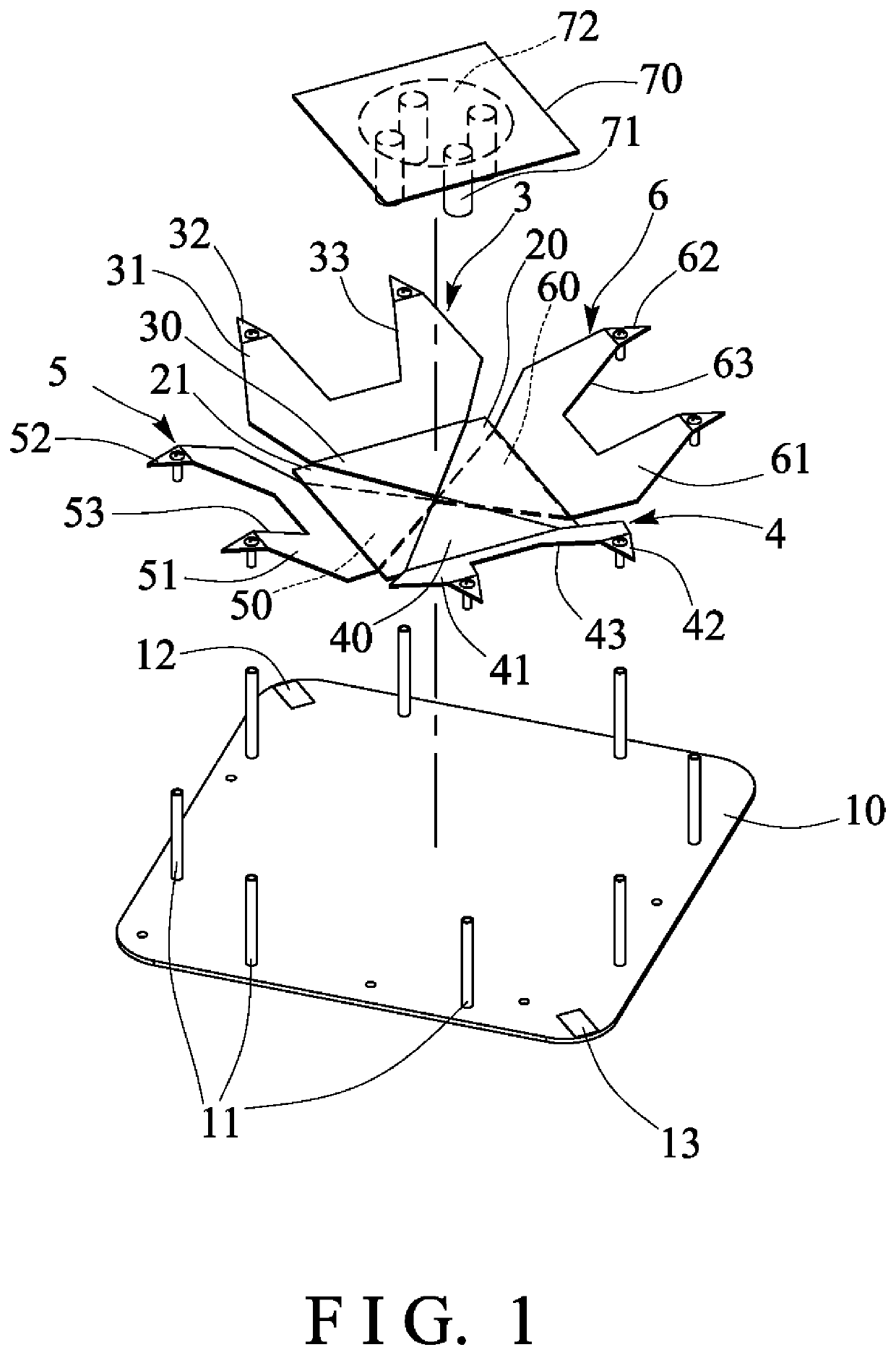
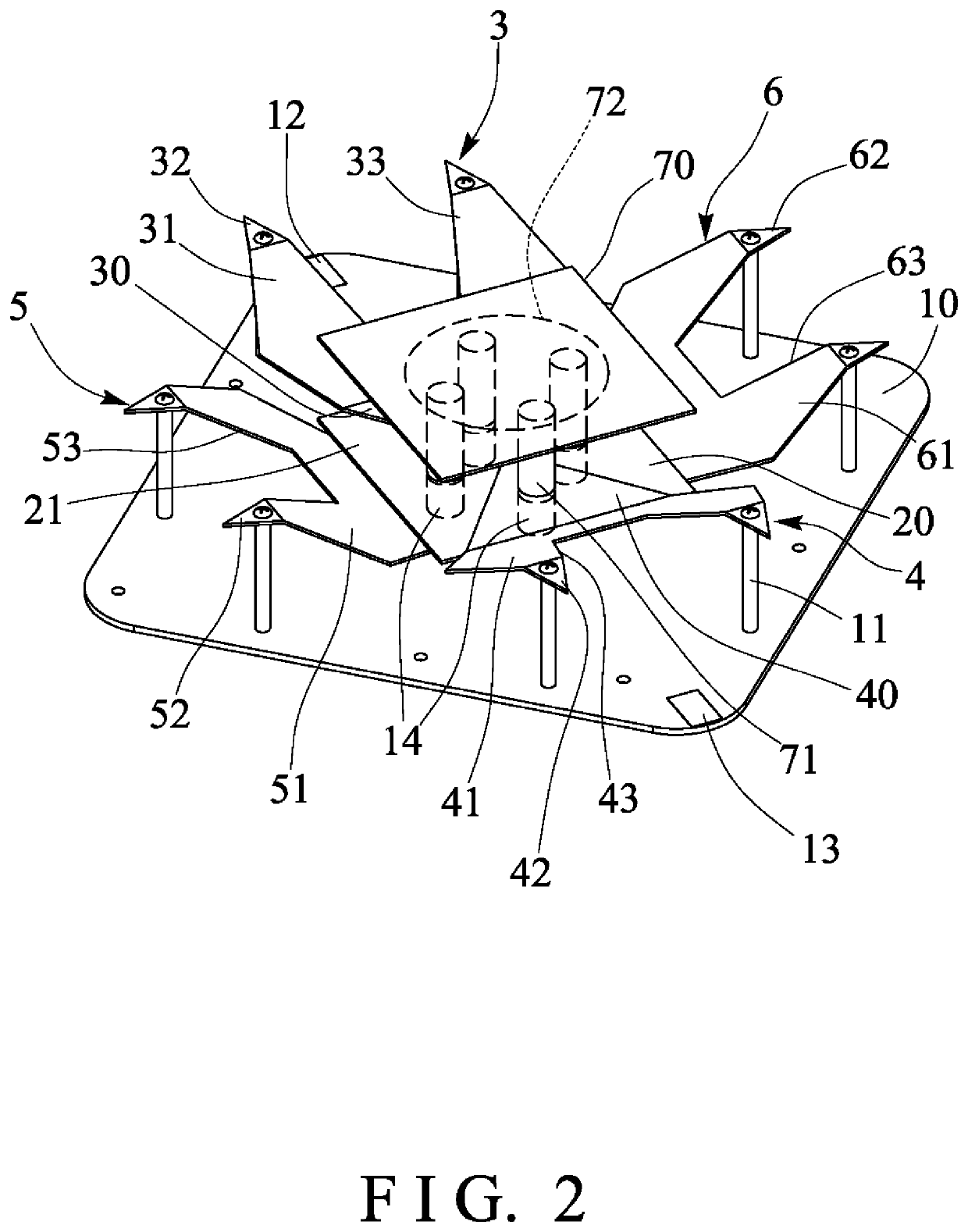
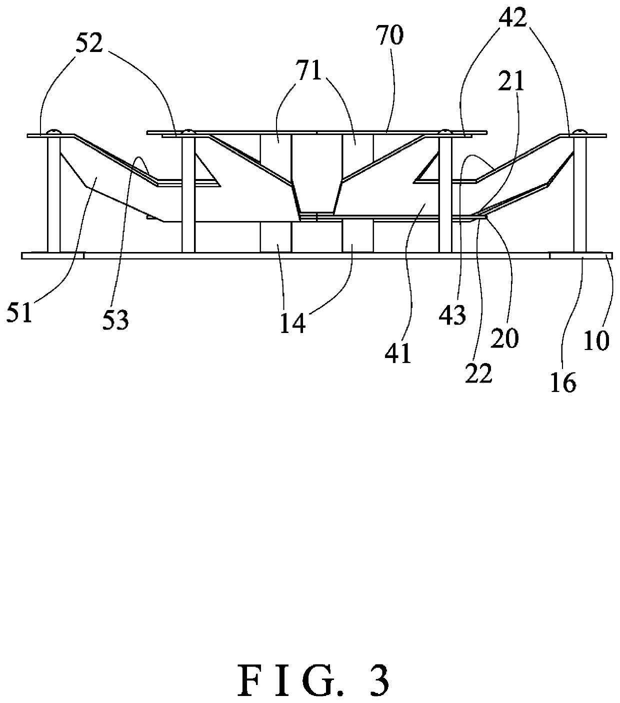
[0028]Referring to the drawings, and initially to FIGS. 1-3, a wideband or dipole antenna device in accordance with the present invention comprises a bottom or base panel 10 including one or more (such as eight or four pairs of) columns or poles 11 extended upwardly therefrom, and preferable, but not necessary that the poles 11 are equally spaced from each other, and further including one or more (such as two) antenna matching components or conductors 12, 13 formed or provided thereon, such as disposed and arranged or located opposite to each other, and such as disposed at the two opposite corner areas. A base substrate 20 is disposed and supported on or above the base panel 10 with one or more (such as four) poles or studs 14 and spaced or separated from the base panel 10, best shown in FIG. 3.

[0029]One or more (such as two pairs or four) radiators 3, 4, 5, 6 are disposed and supported on or attached or mounted or secured to the base substrate 20. For example, the first and the sec...


PUM


Abstract

An antenna device includes a base substrate supported on a base panel, four radiators each include an inner segment located on the base substrate, a middle segment extended from the inner segment, and an outer segment extended from the middle segment, a grounded radiating member is disposed on the bottom surface of the base panel, two feeds disposed on the bottom surface of the base panel and each having a grounded end connected to the grounded radiating member, and two radiating elements disposed on the bottom surface of the base panel, and each having a central portion connected to the feed end of the feed, and two bending sections coupled to the central portion of the radiating element, two outer sections coupled to the bending sections.

Description

BACKGROUND OF THE INVENTION1. Field of the Invention[0001]The present invention relates to a wideband or dipole antenna device, and more particularly to a wideband or dipole antenna device including an improved and simplified structure or configuration for suitably receiving dipole radiation pattern and for solving the problem of the limited bandwidth of the conventional antennas.2. Description of the Prior Art[0002]Various kinds of typical wideband or dipole antenna devices have been developed and provided for wireless communication purposes and the typical wideband or dipole antenna devices cover different spectrums to meet demands of multimedia wideband communication, such as 2G / 3G / 4G wireless communication protocols, Wi-Fi, Global Position System (GPS), and the like.[0003]For example, U.S. Pat. No. 7,990,332 B1 to Tischer, U.S. Pat. No. 8,957,824 B2 to Choi et al., U.S. Pat. No. 9,478,871 B2 to Hsu et al., U.S. Pat. No. 9,590,320 B2 to Zhang et al., U.S. Pat. No. 9,966,664 B2 to...

Claims


Application Information

Patent Timeline
IPC IPC(8): H01Q21/06H01Q5/40H01Q1/36H01Q19/10H01Q9/28H01Q21/26
CPCH01Q9/285H01Q21/26H01Q5/40H01Q1/36H01Q19/108H01Q21/062H01Q1/48H01Q21/28
Inventor CHEN, SHAO YILEE, YUAN-LUNG
Owner JOYMAX ELECTRONICS CO LTD
Why Eureka
Try Eureka