Floating support structure for offshore wind turbine and method for installing a wind turbine provided with such a support structure

a technology for offshore wind turbines and support structures, which is applied in the manufacture of wind turbines, waterborne vessels, wind energy generation, etc., can solve the problems of limiting the usability of offshore wind turbines, limiting the speed of displacement of these platforms, and the use of large-capacity crane vessels, which are rare and expensive to install wind turbines, etc., to prevent the stress of swell, increase the stability of rotation, and reduce the mass of materials for the manufacture of this support structures

Active Publication Date: 2020-12-17
SAIPEM SA
View PDF0 Cites 2 Cited by
  • Summary
  • Abstract
  • Description
  • Claims
  • Application Information

AI Technical Summary

Benefits of technology

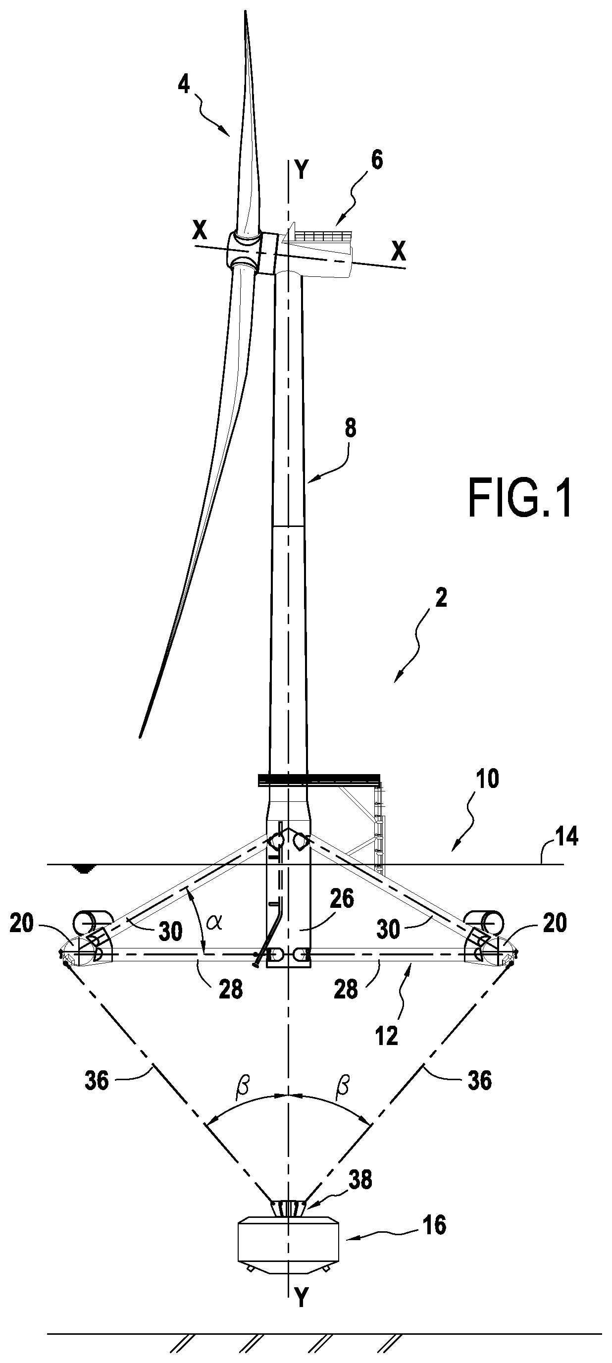
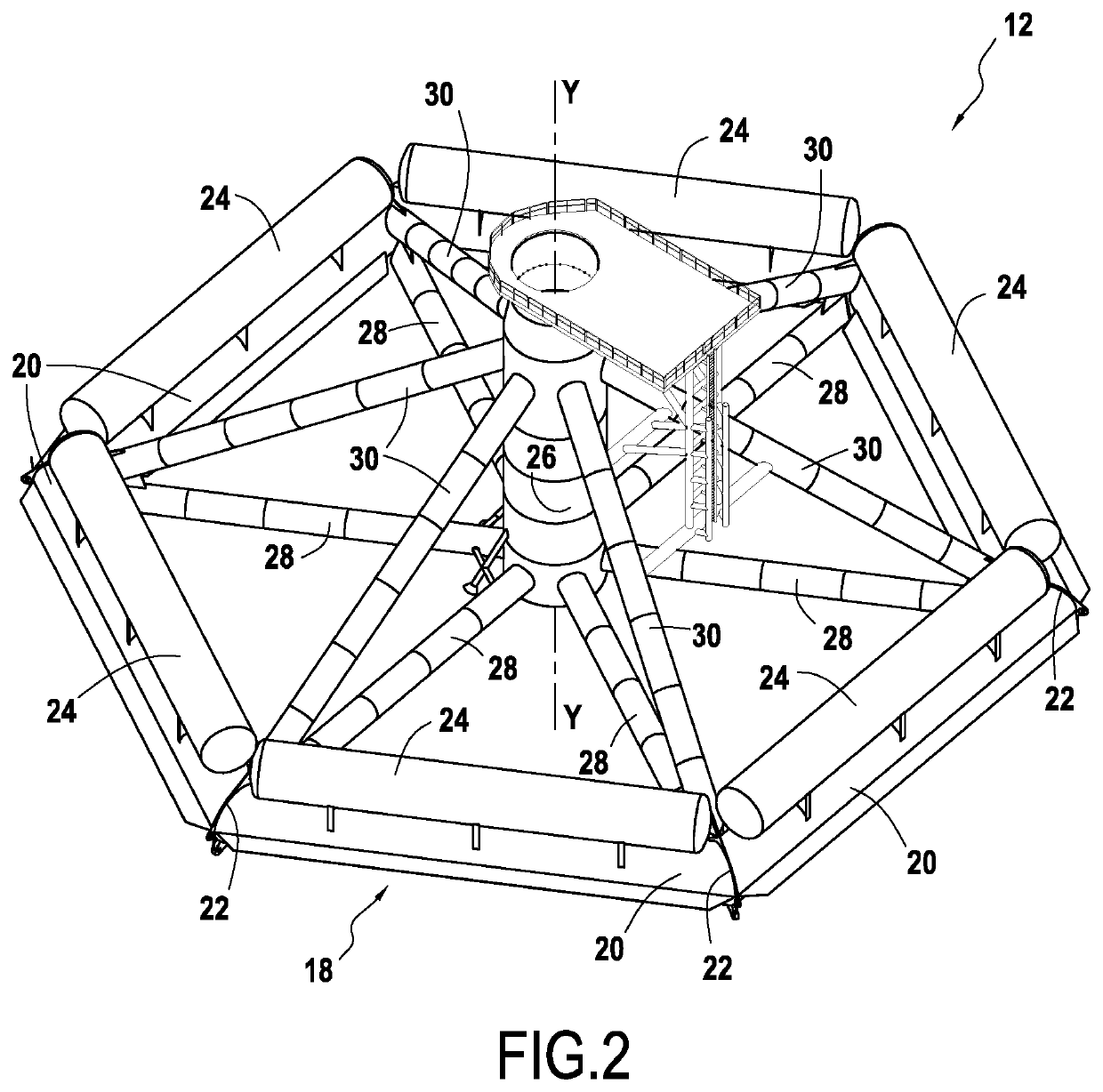
[0013]Furthermore, the particular shape of the main structure of the float makes it possible to obtain buoyancy which is continuously distributed about the vertical axis, and not punctual buoyancy. Likewise, this shape continuity makes it possible to prevent the stresses of the swell on the float from varying with the incidence variations, unlike a float which would be of punctual distribution.
[0014]In addition, such a structure makes it possible to resort to a float immersion depth which is typically comprised between 15 and 30 m. At such a depth, due to the shape continuity of the main float structure, the floating support structure is almost transparent to the effects of the swell and surface flows, which allows the wind turbine to overcome the maximum dynamic stability problems. More generally, the wind turbine using such a floating support structure can be implanted in economically accessible areas because a minimum water depth of the order of 70 m will suffice.
[0015]In this way, the floating support structure according to the invention allows the exploitation of the wind power for electricity production purposes by water depths greater than 70 m, without any upper limit of water depth. The wind turbine using such a floating support structure can therefore be implanted in economically accessible areas.
[0016]The floating support structure according to the invention makes it possible to obtain increased stability in rotation at the level of the wind turbine, both in movement and in acceleration. The mass of materials for the manufacture of this support structure is relatively low, which reduces the manufacturing costs. This floating support structure is also compatible with all current designs of floating wind turbines, with rated power up to 9.5 MW. The structure remains compatible with future wind turbines with a power from 10 to 15 MW and more which should go into production in the coming years.
[0017]The structure according to the invention provides great stability to the supported wind turbine both in the amplitude in rotational movements and in the angular accelerations. This stability relating to the swell, wind and flow conditions encountered in different regions of the world remains compatible with the technical specifications of wind turbines in the offshore wind power industry.
[0018]The structure according to the invention requires minimized tension levels in the anchor lines retaining the wind turbine. In addition, it is compatible with industry standard export power cable designs. It minimizes the surface coverage on the free surface, does not physically interfere with the navigation of small vessels in the immediate vicinity, and minimizes the mass of structural materials used by the floating support structures of wind turbines.

Problems solved by technology

The spar platforms, however, have a number of drawbacks which highly limit their usability in the offshore wind energy sector.
In addition, resorting to spar platforms requires the use of large-capacity crane vessels which are rare and expensive to install the wind turbines on the offshore platforms.
In addition, the spar platforms have a large drag in the water which limits the speeds of displacement of these platforms when they are towed.
These drawbacks of the spar platforms limit the implantation of wind turbines in areas having a fjord as a logistics base, which in practice is found in few places in the world, except in Norway.
In addition, the costs achievable by platforms (due in particular to the very large amount of steel in light of the floatation needs) are limited to high values.
Furthermore, the stability of a floating wind turbine can be composed of a static stability problem and a dynamic stability problem.
The problem of the dynamic stability stems from temporally non-constant forces that exert a destabilizing torque for the structure, inducing movements.
The floating support structures located mainly close to the free surface such as barges or semi-submersible platforms are highly subjected to the waves, so that these structures are generally affected by dynamic stability problems.

Method used


Image

  • Floating support structure for offshore wind turbine and method for installing a wind turbine provided with such a support structure
  • Floating support structure for offshore wind turbine and method for installing a wind turbine provided with such a support structure
  • Floating support structure for offshore wind turbine and method for installing a wind turbine provided with such a support structure

Examples


first embodiment

[0073]In connection with FIGS. 6A to 6Q, there will be described a method for installing, according to the invention, an offshore wind turbine provided with a floating support structure as described above.

[0074]FIGS. 6A to 6H illustrate the different steps of preparation and installation on the seabed of the counterweight of the floating support structure according to the invention.

[0075]In FIG. 6A, a barge 100 transporting in particular the basket 32 of the counterweight of the floating support structure and a deadman 104 is brought into sea on site. The deadman 104 is then descended into sea vertically to the barge 100 by a crane 106 (FIG. 6B) and then placed on the seabed (FIG. 6C).

[0076]A remotely operated vehicle 108 (also called ROV) to supervise these operations and then to install a buoy rope 110 on the deadman 104 is represented in FIG. 6D. Here, the buoy rope 110 is a rope connected to a temporary buoy on the one hand and to a deadman 104 on the other hand, in order to pro...

second embodiment

[0085]In connection with FIGS. 7A to 7K, there will now be described a method for installing, according to the invention, an offshore wind turbine provided with a floating support structure as described above.

[0086]During a first step (FIG. 7A), a barge 200 prepares the temporary area of the seabed in order to allow it to withstand the weight of the baskets filled with ballast of the counterweights of several floating support structures. This preparation consists in discharging on the seabed a filling material allowing the seabed to be able to withstand the weight of the baskets loaded with ballast material while keeping acceptable attitude stability.

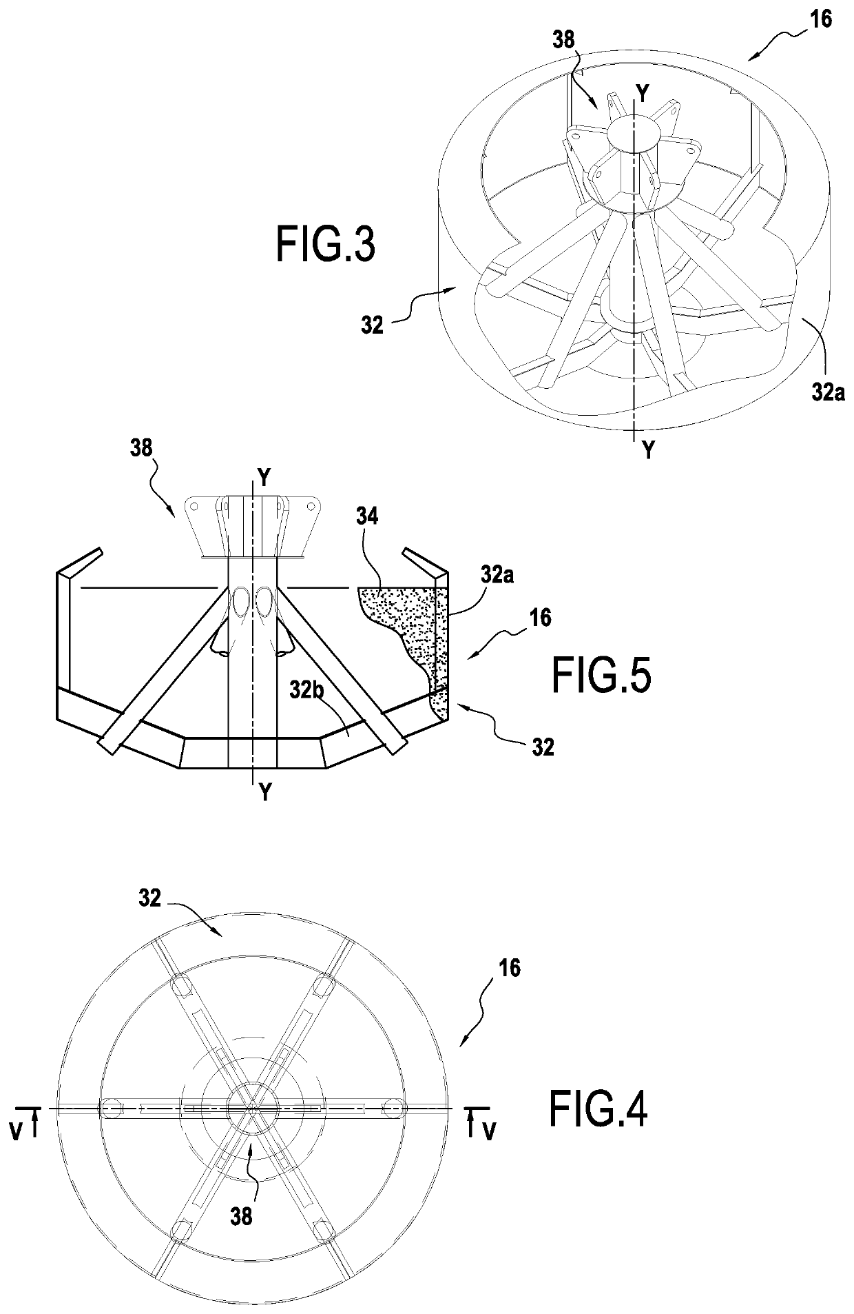
[0087]Once the seabed is prepared, a set of empty baskets 32 of counterweights are descended into the sea from the barge 200 and placed on the seabed using a crane 202 (FIG. 7B). The counterweight baskets are placed one after the other during the progression of the barge, their number depending on the number of offshore wind turbines of...

third embodiment

[0097]In connection with FIGS. 8A to 8H, there will be described the method for installing, according to the invention, an offshore wind turbine provided with a floating support structure as described above.

[0098]This variant is particularly advantageous for the dynamic behavior of the counterweight during the descent by linking the basket of the latter to the float by means of several catenary chains, which makes it possible to decouple the movements of each of them. In addition, no preparation of the seabed is required.

[0099]According to a first step illustrated in FIG. 8A, a first tug 300 is used to tow at sea the float 12 of the floating support structure on which the mast of a wind turbine 2 has been previously mounted. The empty basket 32 of the counterweight of the floating support structure is in for its part towed independently by a second tug 302.

[0100]Note that to facilitate the towing of the basket of the counterweight, the latter can be provided with temporary buoys 304...


PUM


Abstract

A floating support structure for an offshore wind turbine, comprises a float intended to be partly immersed and on which a wind turbine mast is intended to be assembled, and a counterweight connected to the float and intended to be immersed under the float. The float comprises a toroid or polygon-shaped main structure with at least five sides, a central tubular structure having a diameter adapted to receive the mast of the wind turbine and comprising a section able to be ballasted in order to adjust the waterline of the float, a first series of horizontal struts distributed about a vertical axis and connecting the main structure to the central structure, and a second series of oblique struts distributed about a vertical axis and connecting the main structure to the central structure at an angle comprised between 15° and 60° with the horizontal struts.

Description

BACKGROUND OF THE INVENTION[0001]The present invention relates to the general field of offshore wind turbines, that is to say implanted off the coast, and more particularly to floating support structures for floating offshore wind turbines. The invention also relates to a method for installing an offshore wind turbine provided with such a support structure.[0002]An offshore wind turbine aims at using the energy of the wind in order to produce electricity by means of a turbine and an electric generator. There are two main types of offshore wind turbines: fixed wind turbines which are implanted on the seabed (at shallow depths typically less than 50 m), and the floating wind turbines which offer the advantage of being able to be built on land and implanted in areas where the depth of the seabed typically exceeds 50 m.[0003]The floating wind turbines comprise a turbine generally formed by a motor having several rotary vanes with a horizontal axis and an electric generator coupled to th...

Claims


Application Information

Patent Timeline
Patent Type & Authority Applications(United States)
IPC IPC(8): B63B35/44F03D13/25B63B77/10
CPCB63B77/10F05B2230/60B63B2035/446F03D13/25B63B35/44B63B2001/126B63B2241/12Y02E10/72Y02E10/727B63B75/00B63B77/00B63B73/43F03D13/40F05B2240/95F05B2240/93
Inventor COLMARD, CHRISTOPHEFRANC, PAULLE CLEZIO, JEAN-BAPTISTEGENTIL, FRÉDÉRICDELAHAYE, THIERRYCHAZOT, NICOLASHALLOT, RAYMOND
Owner SAIPEM SA
Why Eureka
Try Eureka