Door handle lock and locking method

Active Publication Date: 2020-12-17
NINGBO EUDEMON CHILD PROTECTIVE EQUIP CO LTD
View PDF0 Cites 1 Cited by
  • Summary
  • Abstract
  • Description
  • Claims
  • Application Information

AI Technical Summary

Benefits of technology

The door handle lock described in this patent has a simplified structure that makes it difficult for a child to unlock. It includes a locking part that engages with a movable part to lock the first lock body. The rotation of the door handle is limited by the first lock body. The movable part is mounted on two opposite sides of the first lock body, making it difficult for one finger to unlock. When the convex parts abut against each other, the displacement of the movable part is limited by the cylinder. Overall, this door handle lock has improved security and prevents unauthorized access.

Problems solved by technology

Children's safety problems are relatively trivial.
For example, a child is prone to safety problems when he / she runs out by turning the door lock open without being noticed by his / her guardian.

Method used


Image

  • Door handle lock and locking method
  • Door handle lock and locking method
  • Door handle lock and locking method

Examples


example 1

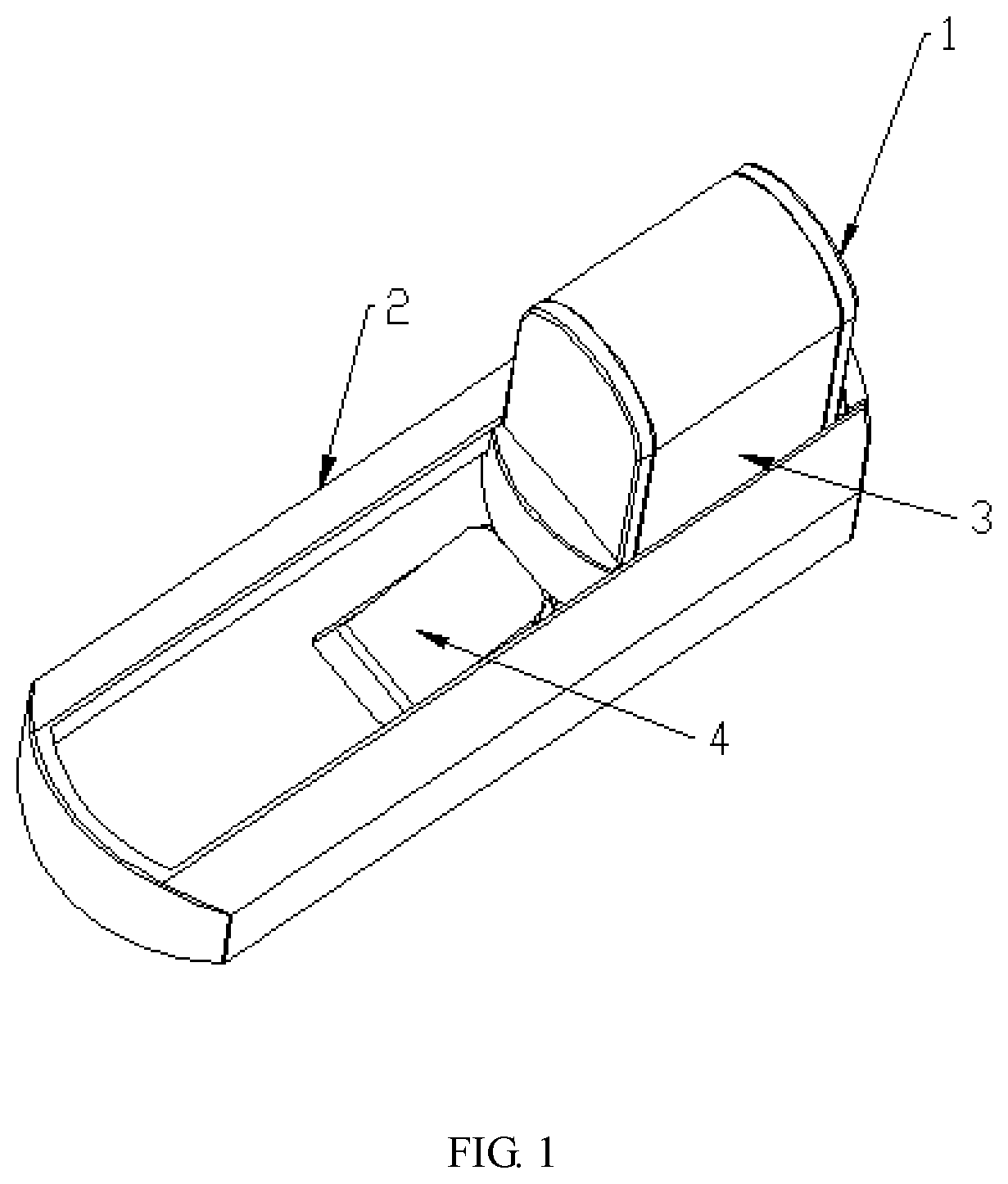
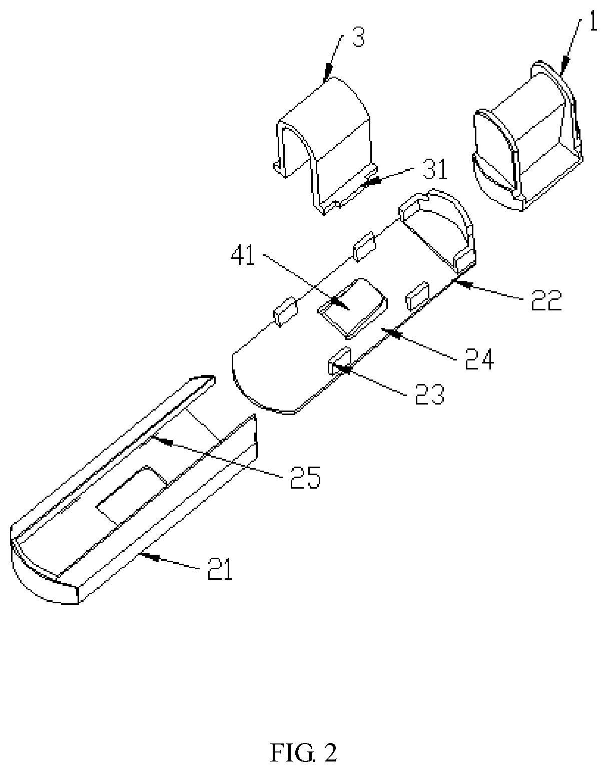
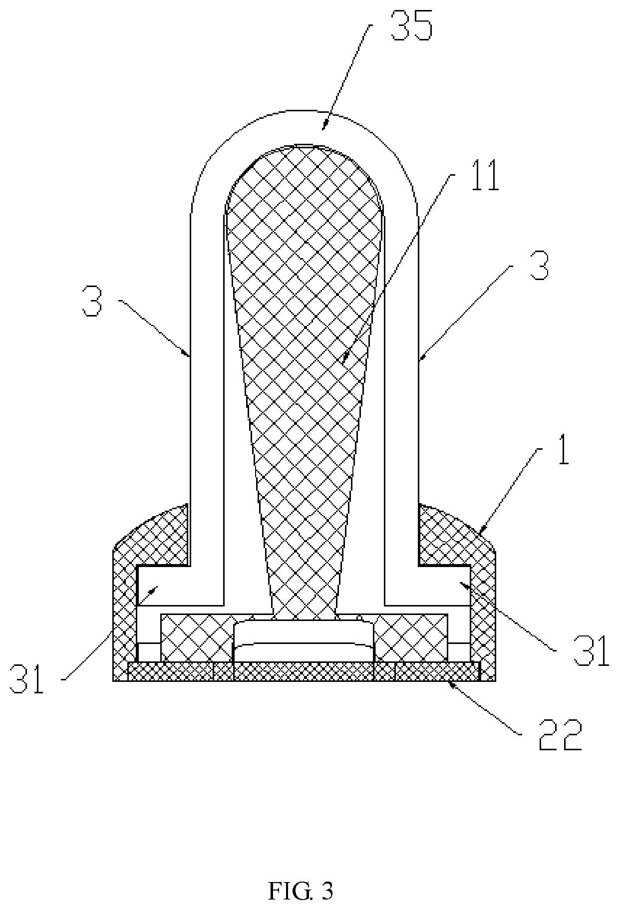
[0084]Referring to FIG. 1, in this example, the door handle lock includes a first lock body 1, a second lock body 2, and a locking part 4. Referring to FIG. 2 and FIG. 3, the first lock body is an integrated structure and is T-shaped on the whole. The longitudinal part of the T-shaped body is a fan-shaped body 11. In this example, the movable part 3 is plate-like, the movable parts on two opposite side surfaces of the T-shaped first lock body are connected into a whole and form a U shape. The U-shaped body 35 is directly fixed to the longitudinal part of the T-shaped body by embedment, that is, the top of the longitudinal part of the T-shaped body is concave, and the inverted U-shaped body is directly embedded in and fixed to the concave part of the longitudinal part of the T-shaped body. Two longitudinal surfaces of the U-shaped body form the movable parts, and a convex part is disposed at the bottom of the longitudinal surface to form a convex member 31.

[0085]Referring to FIG. 2 a...

example 2

[0092]Referring to FIG. 6, compared with Example 1, in this example, the locking part 4 is mounted onto the first lock body 1. Referring to FIG. 7 and FIG. 8, the first lock body is T-shaped, and its transverse part is slotted to form a mounting hole 11 for mounting the locking part 4. The locking part is a prism. In this example, a quadrangular prism and a cuboid are selected, and the middle part hereof is concave so that the surface of the cuboid is concave and convex. The longitudinal part of the T-shaped first lock body is a fan-shaped body. In this example, two movable parts 3 are integrated into a U-shaped body, the U-shaped body 35 is fixed to the longitudinal part of the T-shaped body by embedment, and a hole is opened on an inner side surface of the movable part corresponding to a projecting position of the locking part, i.e., the position of the projecting part at the tail end of the locking part. When the projecting part at the tail end of the locking part does not corres...

example 3

[0096]Referring to FIG. 9 and FIG. 10, compared with Example 2, in this example, a left part 12 and a right part 13 of the first lock body are fixed by embedment. A surface of the left part facing the right part is provided with a convex part and a concave part that are distributed vertically. The corresponding surface of the right part is correspondingly provided with a concave part 15 and a convex part 14, for fixing by embedment. In this example, two movable parts are integrated into a U shape. The slot of the U-shaped body is provided with holes spaced apart by a partition 33. During mounting, the concave part at the upper portion of the left part of the first lock body passes through the hole to be fixed to the convex part of the right part by embedment, and the concave part at the lower portion of the right part of the first lock body passes through the slot of the U-shaped body to form a fan-shaped body with the convex part of the left part by embedment. This structure improv...


PUM


Abstract

A door handle lock and a locking method are provided. The door handle lock comprises a first lock body, a second lock body, and a locking part, and the locking part is engaged with a movable part to lock the first lock body, thus being difficult to unlock. The door handle lock is mounted within a rotation range of the door handle, and the rotation of the door handle is limited by the first lock body. Such a setting effectively prevents a child from unlocking without permission and then opening the door to escape, thus improving the security.

Description

TECHNICAL FIELD[0001]The present invention relates to the field of lock devices, and in particular, to a door handle lock and a locking method.BACKGROUND[0002]As is well known, external risk factors have greater impacts on children because their bodies and minds are growing. Children's safety problems are relatively trivial. For example, a child is prone to safety problems when he / she runs out by turning the door lock open without being noticed by his / her guardian. Moreover, most door locks can be unlocked easily only by twisting the door handle. In view of this, a child safety lock emerges on the market, in which two rotary lock bodies are mounted on a carrier to limit the door handle between the two lock bodies to form a limit. The door can be unlocked only by turning the lock body at one side. This unlocking process is simple and can be easily imitated by a child who may further unlock without permission, and thus it needs to be improved.SUMMARY OF THE INVENTION[0003]In view of t...

Claims


Application Information

Patent Timeline
IPC IPC(8): E05B65/00E05B13/00
CPCE05B65/0014E05B13/007E05B13/00E05B15/00E05B13/002
Inventor WANG, ZHANGJUN
Owner NINGBO EUDEMON CHILD PROTECTIVE EQUIP CO LTD
Why Eureka
Try Eureka