High-speed dual turbo machine enabling cooling thermal equilibrium

Active Publication Date: 2020-12-17
TURBOWIN
View PDF0 Cites 2 Cited by
  • Summary
  • Abstract
  • Description
  • Claims
  • Application Information

AI Technical Summary

Benefits of technology

The present invention is designed to solve problems in the related art by providing a dual turbo machine that uses a suction air-cooling method to cool the inside using a shortest path and minimize the flow of air sucked inside. The invention aims to maximize cooling efficiency by making external air, which is sucked in the dual turbo machine to cool the air compressor, flow through a specific path. The invention includes a shortest-path generator to enable smooth circulation of air in the dual turbo machine casing and reduce the contact time between the air compressor and external air sucked into the duoambo machine casing to cool the air compressor.

Problems solved by technology

However, the increase of the technical skills for the turbo machine complicates the structure of the turbo machine, thereby increasing the cost of the turbo machine.
This, rather, decreases the durability and efficiency of the turbomachinery (energy loss due to the complex structure of the turbo machine) and causes a problem in that maintenance and repair due to failure thereof are difficult.

Method used


Image

  • High-speed dual turbo machine enabling cooling thermal equilibrium
  • High-speed dual turbo machine enabling cooling thermal equilibrium
  • High-speed dual turbo machine enabling cooling thermal equilibrium

Examples


Embodiment Construction

[0097]Hereinafter, functions, components, and actions of the high-speed dual turbo machine enabling cooling thermal equilibrium of the present invention will be described in more detail with reference to the accompanying drawings.

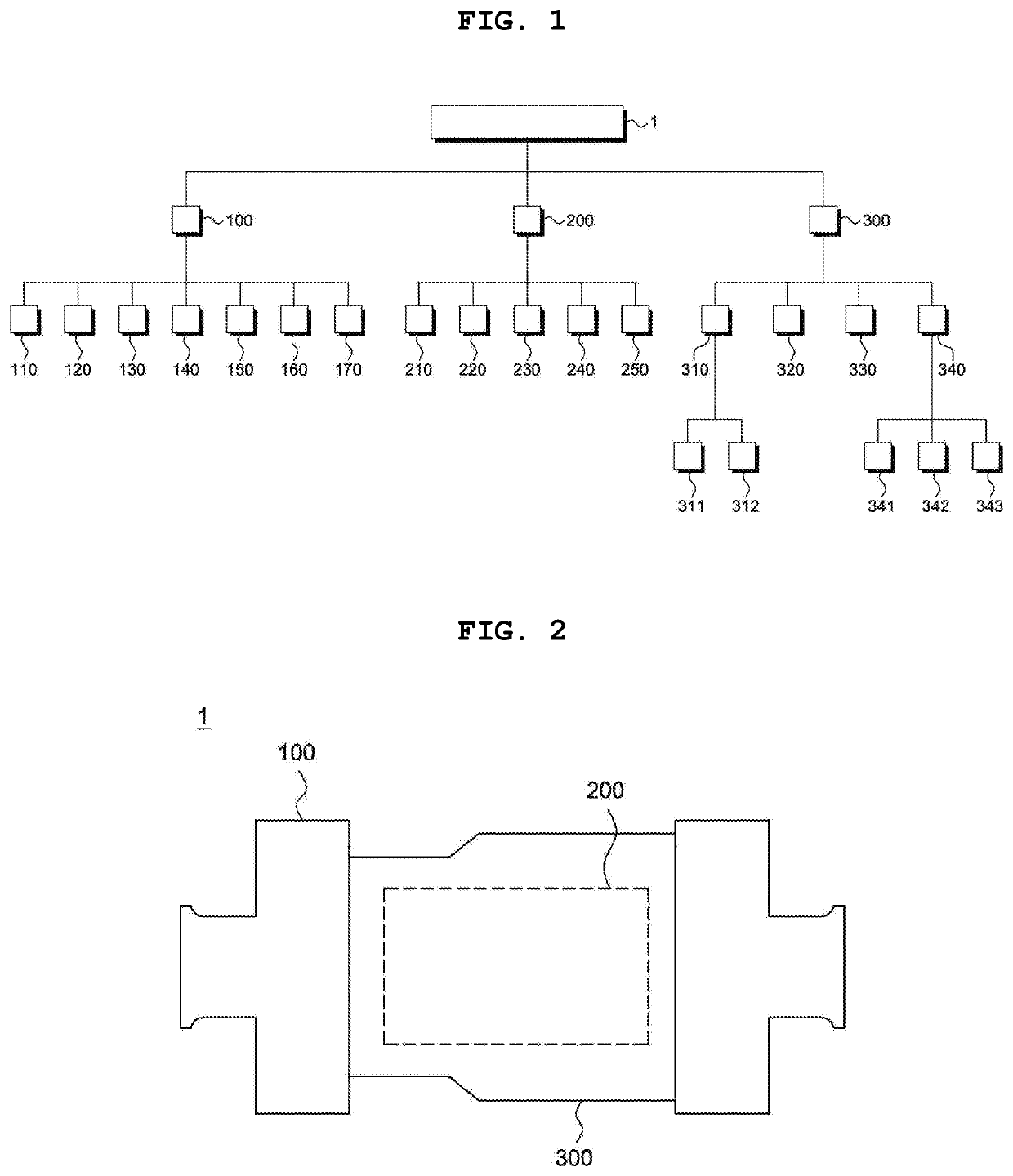
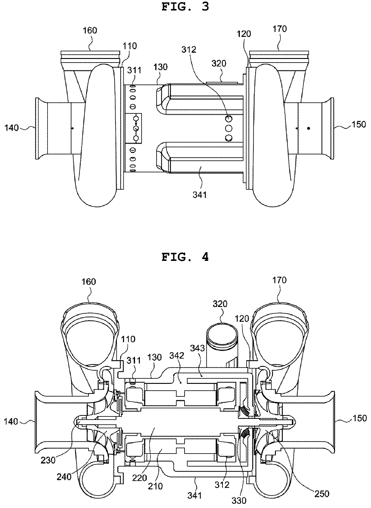
[0098]FIG. 1 is a view showing the configuration of a high-speed dual turbo machine enabling cooling thermal equilibrium of the present invention, FIG. 2 is a schematic view of the high-speed dual turbo machine enabling cooling thermal equilibrium of the present invention, FIG. 3 is a front view of the high-speed dual turbo machine enabling cooling thermal equilibrium of the present invention, and FIG. 4 is a cross-sectional view of the high-speed dual turbo machine enabling cooling thermal equilibrium of the present invention.

[0099]As shown in FIGS. 1 to 4, the present invention relates to a high-speed dual turbo machine (1) enabling cooling thermal equilibrium, the high-speed dual turbo machine including:

[0100]a dual turbo machine casing (100) discharging...


PUM


Abstract

Disclosed is a high-speed dual turbo machine enabling cooling thermal equilibrium and, more particularly, to a high-speed dual turbo machine enabling cooling thermal equilibrium, the high-speed dual turbo machine maximizing the cooling efficiency thereof by compressing and discharging external air suctioned therein at both ends, cooling an air compressor in a suction air-cooling method, decreasing a flow path of air for cooling the inside of the dual turbo machine and the air compressor, and optimizing the flow path.Accordingly, the present invention uses the suction air-cooling method and guides the flow of air for cooling the turbo machine through a specific path, so that it maximizes the efficiency and durability of the turbo machine, the cost reduction owing to the structural simplification of the turbo machine, and the easiness of maintenance by preventing an increase in temperature of the inside of the turbomachine casing (100) and the air compressor (200).

Description

BACKGROUND OF THE INVENTIONField of the Invention[0001]The present invention relates to a high-speed dual turbo machine enabling cooling thermal equilibrium and, more particularly, to a high-speed dual turbo machine enabling cooling thermal equilibrium, the high-speed dual turbo machine maximizing the cooling efficiency thereof by compressing and discharging external air suctioned therein at both ends, cooling an air compressor in a suction air-cooling method, decreasing a flow path of air for cooling the inside of the dual turbo machine and the air compressor, and optimizing the flow path.Description of the Related Art[0002]In general, a turbo machine is an apparatus for compressing a gas by a rotation of an impeller.[0003]Such a turbo machine has already been published in a variety of technologies and many kinds of turbo machines having a suitable shape and a specification suitable for the environment of an industrial site have been released.[0004]Also in order to increase the eff...

Claims


Application Information

Patent Timeline
IPC IPC(8): F02C7/18F02C7/04F02C7/12F02C7/141F01D25/12F01D25/26
CPCF02C7/04F01D25/12F02C7/141F02C7/185F01D25/26F02C7/12F02C7/18F04D29/5806F04D29/582F04D29/284F04D29/441H02K9/06H02K5/20F04D17/105F04D25/163F04D25/0606F04D29/58F05D2210/12F05D2260/201F04D25/082
Inventor KIM, MINSOO
Owner TURBOWIN
Why Eureka
Try Eureka