
Hidden Type Split Hinge

a split hinge, hidden technology, applied in the field of hinges, can solve the problems of increasing increasing the cost of production in the manufacturing process, and increasing the space, so as to increase the overall volume of the hinge, increase the thickness of the plate, and increase the space for accommodating the plate

Active Publication Date: 2020-12-17
JARLLYTEC CO LTD
View PDF0 Cites 15 Cited by
  • Summary
  • Abstract
  • Description
  • Claims
  • Application Information

AI Technical Summary

Benefits of technology

The present invention provides a hidden type split hinge that simplifies the internal gear ring and the movable plate by removing the internal teeth or rib structure. This reduces the overall thickness by eliminating the need for internal teeth and reduces the size of the hinge components, thereby increasing the selling volume and reducing production cost.

Problems solved by technology

However, the use of internal teeth or ridges provided on curved plates not only increases the thickness of plates, but also increases the space for accommodating the plates, thereby the overall volume of hinges is increased, and cost of production will be increased in manufacturing process because it is required to improve precision.

Method used


Image

  • Hidden Type Split Hinge
  • Hidden Type Split Hinge
  • Hidden Type Split Hinge

Examples


Embodiment Construction

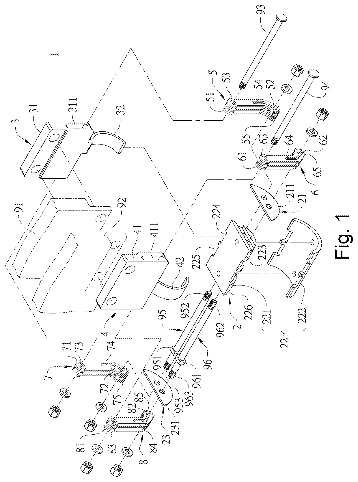
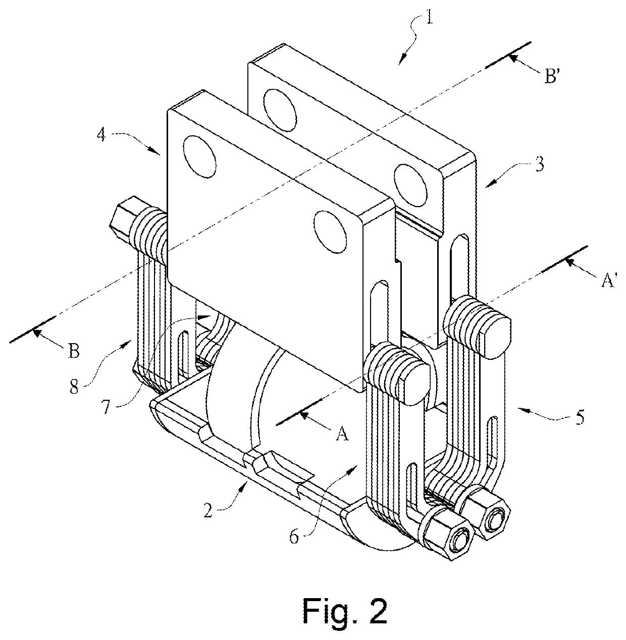
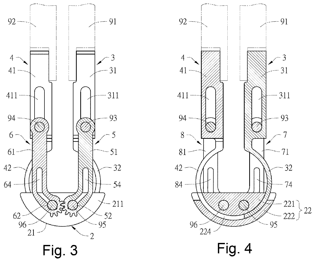
[0027]Please refer to FIGS. 1-4, which are preferred embodiments of a hidden type split hinge 1 of the present invention, including a curved seat body 2, a first rotating member 3, and a second rotating member 4, a first torsion unit 5, a second torsion unit 6, a third torsion unit 7, and a fourth torsion unit 8. A first connecting portion 31 of the first rotating member 3 is connected to a lateral surface of a first bracket 91 of a display of an electronic device, and the second connecting portion 41 of the second rotating member 4 is connected to a lateral surface of a second bracket 92 of a base of the electronic device, thereby when the first rotating member 3 and the second rotating member 4 are respectively rotated relative to each other around the curved seat body 2 as an axis, the display and the base are rotated in a reverse direction. In one embodiment, the first connecting portion 31 of the first rotating member 3 and the second connecting portion 41 of the second rotatin...


PUM


Abstract

The present invention provides a hidden type split hinge. First and second curved tracks are provided on a curved seat body for respectively limiting a first and second curved blocks of first and second rotating members in a way of being relatively swung. First and second torsion units are symmetrical and adjacently provided to a first side of the curved seat body, and one end of the first and second torsion units is respectively provided with first and second pivoting holes, and the first and second pivoting holes are respectively in communication with first and second elongated opening holes, first and second tooth portions are respectively provided around peripheries of the first and second pivoting holes, and the first tooth portion is engaged with the second tooth portion, and the first and second pivoting hole are axially connected to the first and second shaft ends of a first lateral surface.

Description

FIELD OF THE INVENTION[0001]The present invention relates to a hinge, and more particularly to a hidden type split hinge for a foldable electronic device.BACKGROUND OF THE INVENTION[0002]For conventional foldable electronic devices, for example, for displays and bases of notebooks, a single-axial hinge is used to connect the bases with a side of the display to form a pivoting connection, so that the notebooks can be folded or unfolded. In addition to the conventional notebooks, especially for the existing dual-touch screen computers, the current foldable design is mainly to improve the shortcoming of the dual-touch screen computers. The two screens of the existing dual-touch screen computers, the two screens can be moved to approach each other during the folding process, so as to reduce the gap between them and to avoid exposure of the internal structures of hinges or pivot points.[0003]For example, the Chinese Utility Model Patent entitled with “Hinge device and electronic apparatu...

Claims


Application Information

Patent Timeline
Patent Type & Authority Applications(United States)
IPC IPC(8): F16C11/04E05D3/14E05D3/18E05D11/06G06F1/16
CPCE05Y2900/606E05D3/18G06F1/1681E05D3/14E05D11/06E05Y2201/224F16C11/04F16C2226/76F16C2226/62F16C2361/61E05Y2201/716E05Y2999/00
Inventor CHANG, JUI-HUNGCHANG, HSIN-CHUNG
Owner JARLLYTEC CO LTD
Learn More