Snap button device for non-destructive characterization of materials

Pending Publication Date: 2020-12-24
TIMPONE FRANCESCO +2
View PDF5 Cites 2 Cited by
  • Summary
  • Abstract
  • Description
  • Claims
  • Application Information

AI Technical Summary

Benefits of technology

The present invention provides a device for viscoelastic characterization of materials that allows for easy replacement of springs with different rigidity to vary potential energy applied to the test material. The device also allows for variation in free motion frequency but not forced motion frequency to minimize the number of elements and make it more cost-effective, functional, and portable. Additionally, the device can control the temperature of the material for increased accuracy and can be positioned accurately in relation to the tire to consider the angle between the trajectory of mass stroke and the direction of the load force for a defined fall force.

Problems solved by technology

Disadvantageously however the load is released manually by the operator.
In this way, it is not sure that the potential energy is always the same, in fact the operator could slow the load falling by using fingers.
As a consequence, the calculation of the material index is not exact since the impact speed is not always the same but subjected to a possible mistake of the operator, therefore it can be said that such a system is operator-dependent.
There exist also other measurement systems whose architecture is more complex and requires test benches which make these systems cumbersome and very expensive.
Therefore, there remains unresolved the problem to provide a device for viscoelastic characterization of materials, and in particular of tires, which overcomes the limits of the devices known at the state of the art, and which is in particular cheap, portable and which allows to obtain test results nondependent on the operator manual skill.

Method used


Image

  • Snap button device for non-destructive characterization of materials
  • Snap button device for non-destructive characterization of materials
  • Snap button device for non-destructive characterization of materials

Examples


Embodiment Construction

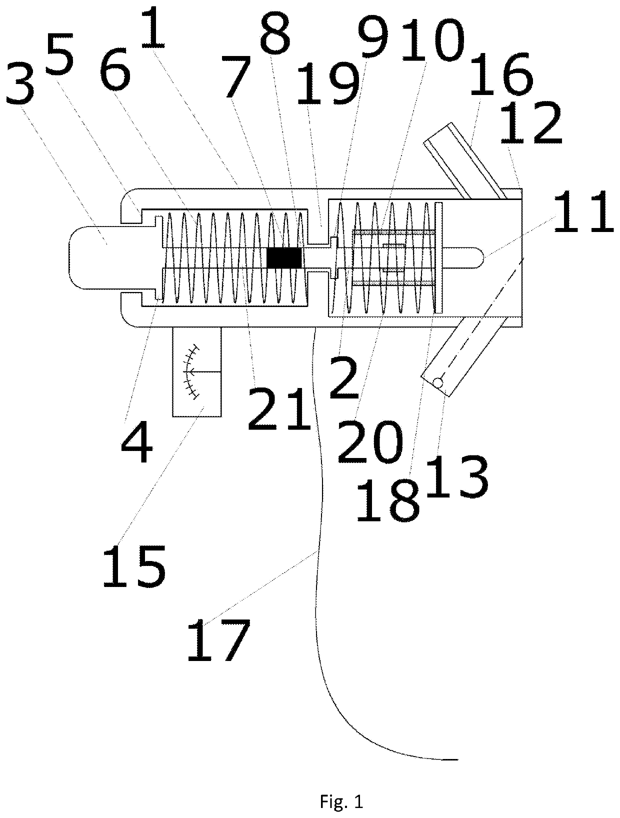
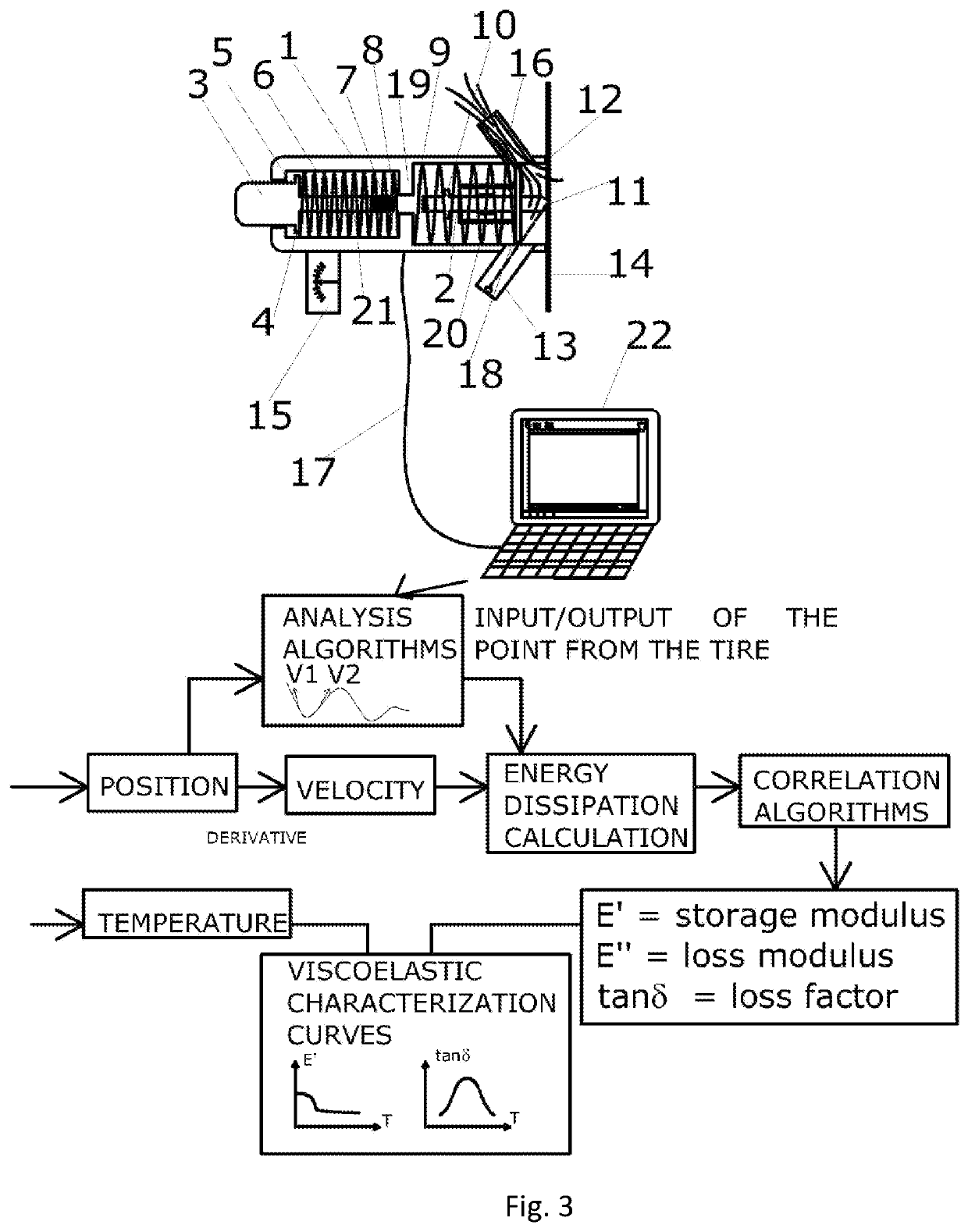
[0016]As it is shown in the appended FIG. 1, the device for nondestructive viscoelastic characterization of materials according to the invention comprises:[0017]a tubular shell (1), almost cylindrically shaped and such dimensioned that it can be grasped by hand, having inside a through-recess provided with at least a first shrinkage (19), also called step, provided inside the axial development of said inner recess and a second shrinkage (5) provided at the upper base of said shell (1);[0018]a first rod (2), provided at an end with a cap (18) and a ferrule (11) projecting to the same, and at the other end with a base of ferromagnetic material (8). The rod (2) is fastened so that it can slide inside said shell (1) between a first position, in which said ferrule (11) does not project to the lower base (12) of said shell (1), and a second position, in which said ferrule (11) projects to the said lower base (12). To such end the rod (2) is provided with a stop; (9) configured to abut sai...


PUM


Abstract

A device for nondestructive viscoelastic characterization of materials, comprising: a tubular shell, having inside a through-recess provided with at least a first and a second shrinkage; a first rod, provided with a base of ferromagnetic material (8), sliding inside said shell between a first position, in which said ferrule does not project to the lower base of said shell, and a second position, in which said ferrule projects to said lower base; a first spring configured to push said ferrule outwards; a displacement sensor configured to read the displacement of said first rod; a button, sliding between a stroke greater than the one of said first rod, and integral to a second rod provided with a magnet and coaxial to said first rod; a second spring.

Description

BACKGROUND OF THE INVENTION1. Field of the Invention[0001]The present invention relates to the technical field comprising measurement devices used for viscoelastic characterization of materials, and in particular of tires for vehicles.[0002]The present invention aims at developing a measurement device which provides parameter values called storage modulus, loss modulus and loss factor of a tire which define their viscoelastic features.2. Brief Description of the Prior Art[0003]The storage modulus measures the stored energy and is linked to the elastic behavior. The loss modulus measures the dissipated energy and is linked to the viscoelastic behavior.[0004]The ratio between loss modulus and storage modulus provides the phase angle tangent between the two modules.[0005]Such aim is reached by means of a device comprising the features described in the main claim. Advantageous embodiments of the invention are described in the dependent claims.[0006]At the state of the art there are know...

Claims


Application Information

Patent Timeline
IPC IPC(8): G01M17/02G01N3/307G01N3/48G01N33/44
CPCG01N2203/0094G01N3/48G01M17/02G01N3/307G01N33/445G01N2203/0035
Inventor TIMPONE, FRANCESCOSAKHNEVYCH, ALEKSANDRFARRONI, FLAVIO
Owner TIMPONE FRANCESCO
Why Eureka
Try Eureka