Supercharge Your Innovation With Domain-Expert AI Agents!

Integrated photosensitive module, photosensitive assembly, camera module and preparation method therefor

a technology of integrated photosensitive modules and camera modules, which is applied in the field of camera modules, can solve the problems of increasing thinness and light, reducing the height and size limits of camera modules, and many relatively fragile but highly sensitive electronic components, and achieves narrower limit width and higher formation precision

Inactive Publication Date: 2020-12-24
NINGBO SUNNY OPOTECH CO LTD
View PDF0 Cites 0 Cited by
  • Summary
  • Abstract
  • Description
  • Claims
  • Application Information

AI Technical Summary

Benefits of technology

The present invention provides an integrated photosensitive module, photosensitive assembly, camera module and preparation method. Compared to existing technology, the present invention has a thinner isolation adhesive layer, reducing the overall thickness and size of the photosensitive assembly. The diameter of the light passing hole gradually decreases from a top side of the molding body toward the light transmitting element. These technical effects provide a more compact and efficient photosensitive module for various applications.

Problems solved by technology

In recent years, with the popularization and development of smart devices, they have become increasingly thin and light.
Due to the limitation of the injection molding process, its height is often at least 200 um or more, which limits the height and size of the camera module to be further reduced, which is contrary to market demand.
For the camera module, it includes many relatively fragile but highly sensitive electronic components, especially photosensitive elements.
In order to meet the two technical requirements at the same time, the range of the non-photosensitive region of the photosensitive element will inevitably be continuously reduced, thereby causing a lot of troubles for forming the isolation adhesive layer.
As the area of the non-photosensitive region shrinks, the possibility of the glue erroneously staining the photosensitive element during the formation of the isolation adhesive layer is greatly increased.
At the same time, due to the reduction of the area where the isolation adhesive layer is laid, the shape and size requirements of the isolation adhesive layer are becoming more and more stringent, especially the thickness requirement of the isolation adhesive layer, which will inevitably increase the performance requirements of the equipment forming the isolation adhesive layer and the glue material forming the isolation adhesive layer, resulting in an increase in process cost.
In addition, due to the performance defects of the existing dispensing equipment and the limitations of the dispensing material, the flatness of the isolation adhesive layer is difficult to guarantee.
Therefore, the isolation adhesive layer and the molding surfaces of the mold die are adhered together to form a sealed environment, the tightness between the flat molding surface and the isolation adhesive layer with a curved surface is difficult to ensure, which may easily cause molding process errors.
In addition, it is also limited by the dispensing material.
When the isolation adhesive layer is pressed by the molding surface of the molding die, it is prone to secondary deformation or even collapse, so that the glue flows to the photosensitive region of the photosensitive element, causing the photosensitive element to be contaminated.
Generally, the ratio of height to width of the isolation adhesive layer after compression is less than that before compression, thus when the isolation adhesive layer is squashed, the widened isolation adhesive layer extends in the non-photosensitive region of the photosensitive element that has been continuously reduced, and easily touches the photosensitive region of the photosensitive element to cause the photosensitive element to be contaminated.

Method used


Image

  • Integrated photosensitive module, photosensitive assembly, camera module and preparation method therefor
  • Integrated photosensitive module, photosensitive assembly, camera module and preparation method therefor
  • Integrated photosensitive module, photosensitive assembly, camera module and preparation method therefor

Examples


Embodiment Construction

[0120]The following description is used to disclose the present invention to enable those skilled in the art to implement the present invention. The preferred embodiments in the following description are only examples, and those skilled in the art can think of other obvious modifications. The basic principles of the present invention defined in the following description can be applied to other embodiments, modifications, improvements, equivalent solutions, and other technical solutions without departing from the spirit and scope of the present invention.

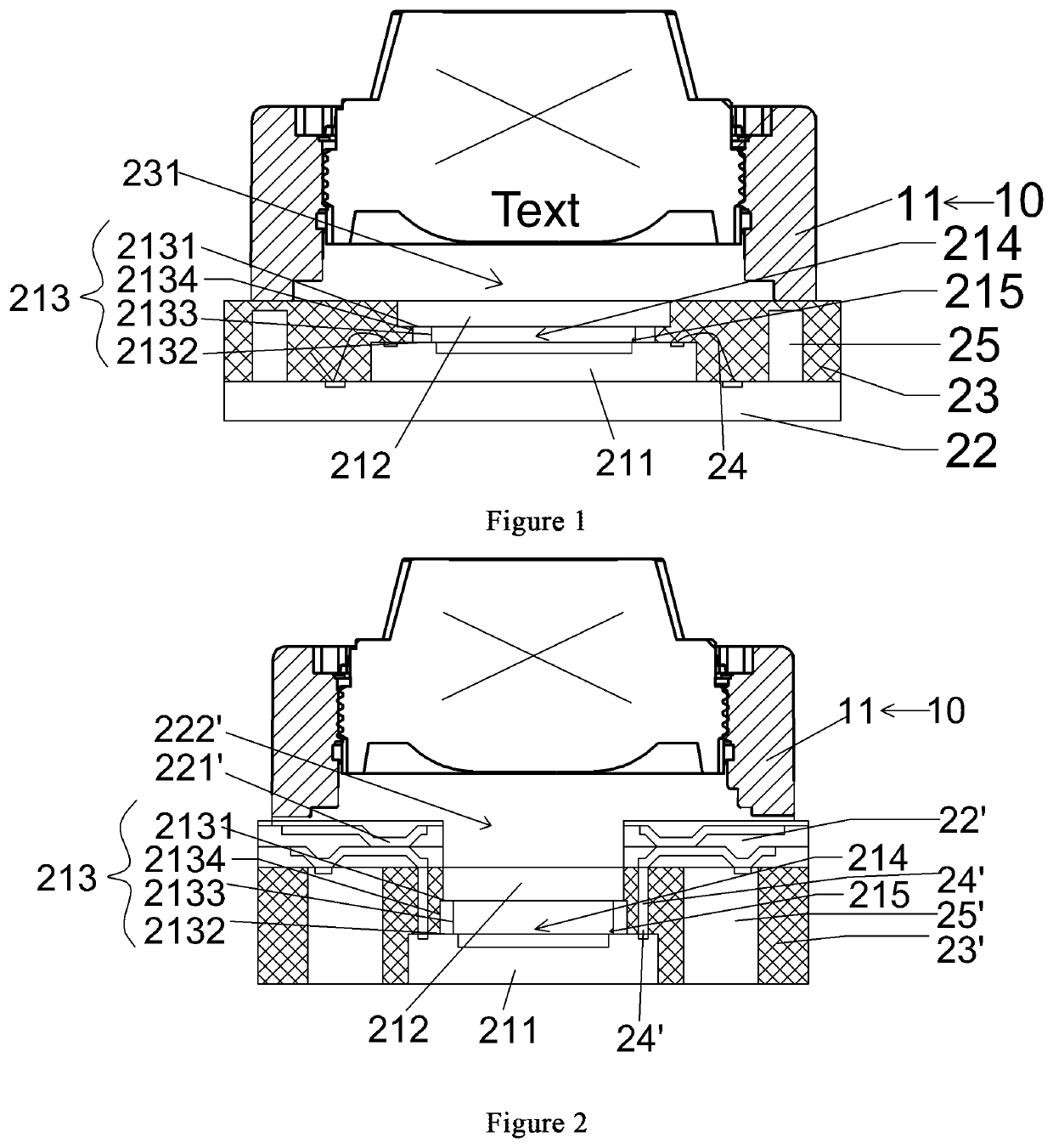
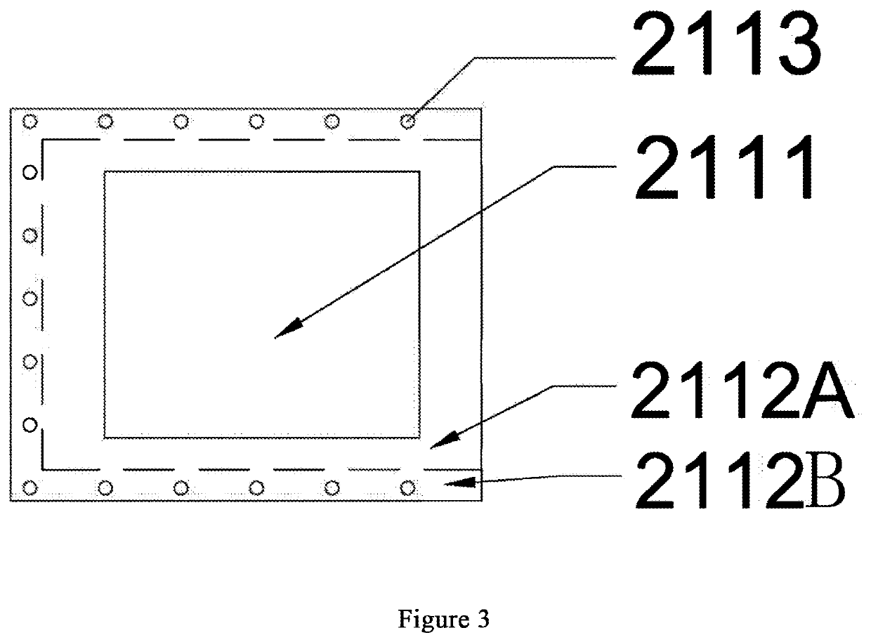
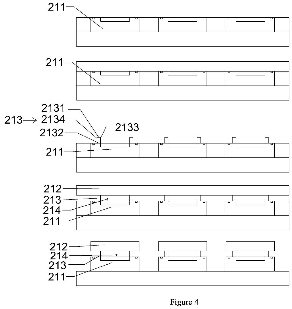
[0121]Those skilled in the art should understand that in the disclosure of the present invention, orientation or positional relationship indicated by the terms “portrait”, “landscape”, “upper”, “lower”, “front”, “rear”, “left”, “right”, “vertical”, “horizontal”, “top”, “bottom”, “inner”, “outer”, etc. is based on the orientation or positional relationship shown in the drawings, which is only for the convenience of describing the pres...


PUM

PropertyMeasurementUnit
heightaaaaaaaaaa
photosensitiveaaaaaaaaaa
non-photosensitiveaaaaaaaaaa

Abstract

Disclosed is a photosensitive module (21), adapted to a camera module, comprising a photosensitive element (211), a light transmitting element (212) and an isolation adhesive layer (213), wherein the photosensitive element has a photosensitive region and a non-photosensitive region, the light transmitting element is arranged in a photosensitive path of the photosensitive element, and wherein the isolation adhesive layer is arranged in the non-photosensitive region and supports the light transmitting element, and the isolation adhesive layer is formed by means of photolithography.

Description

FIELD OF THE INVENTION[0001]The invention relates to field of a camera module, in particular to a photosensitive module in which a light transmitting element is directly provided on a photosensitive element, a photosensitive assembly including the same, a camera module, and a preparation method thereof.BACKGROUND OF THE INVENTION[0002]In recent years, with the popularization and development of smart devices, they have become increasingly thin and light. Correspondingly, camera modules is required to be adapted to be developed, and become more and more multi-functional integration, light and thin, and miniaturization, so that the volume required for the camera module to be assembled in smart electronic device can be reduced accordingly, and meet the imaging requirements of the camera module. Therefore, camera module manufacturers continue to devote themselves to designing and manufacturing camera modules that meet these requirements.[0003]In the prior art, as an essential element, th...

Claims


Application Information

Patent Timeline
Patent Type & Authority Applications(United States)
IPC IPC(8): H01L27/146
CPCH01L27/14625H01L27/14687H01L27/14618H01L27/14685H01L31/0203H01L27/14601H01L27/14683
Inventor WANG, MINGZHUTANAKA, TAKEHIKOYAO, LIFENGHUANG, ZHENGUO, NANLIU, XIAODICHEN, ZHENYU
Owner NINGBO SUNNY OPOTECH CO LTD
Features
  • R&D
  • Intellectual Property
  • Life Sciences
  • Materials
  • Tech Scout
  • Unparalleled Data Quality
  • Higher Quality Content
  • 60% Fewer Hallucinations
Learn More