
Thermoelement (variants)

Inactive Publication Date: 2020-12-24
OBSHCHESTVO S OGRANICHENNOJ OTVETSTVENNOSTYU RUSTEK
View PDF0 Cites 0 Cited by
  • Summary
  • Abstract
  • Description
  • Claims
  • Application Information

AI Technical Summary

Benefits of technology

The present invention aims to improve the heat conversion efficiency of a thermoelectric element by designed variations. The first variant aims to increase the efficiency at the initial phase of conductivity, typically at temperatures between 100-0 C. The second variant aims to improve the efficiency across the entire operating temperature range.

Problems solved by technology

High-priority problem in thermoelectric power generation technology is improving thermoelectric efficiency of a thermoelectric device.
However, strong temperature dependence of Z parameter is a limitation of such materials.

Method used


Image

  • Thermoelement (variants)
  • Thermoelement (variants)
  • Thermoelement (variants)

Examples


first embodiment

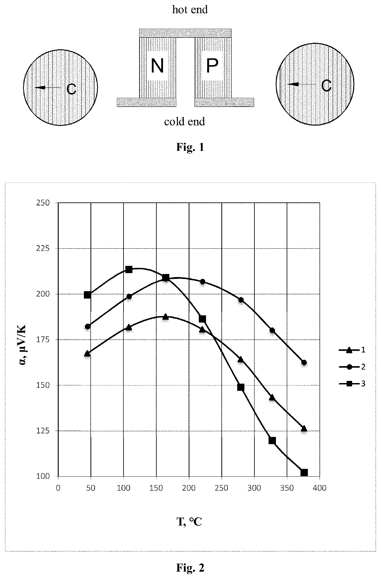
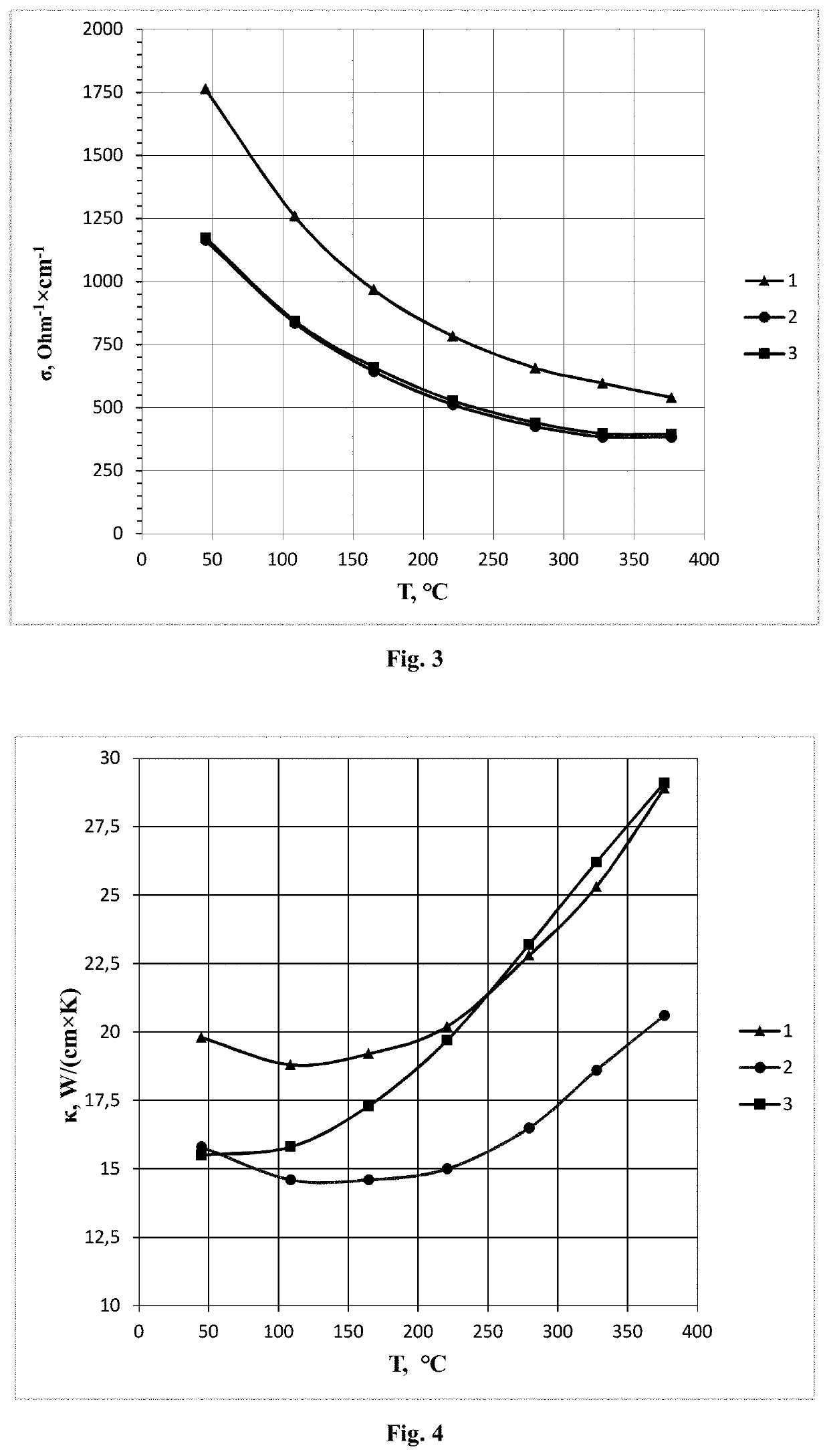
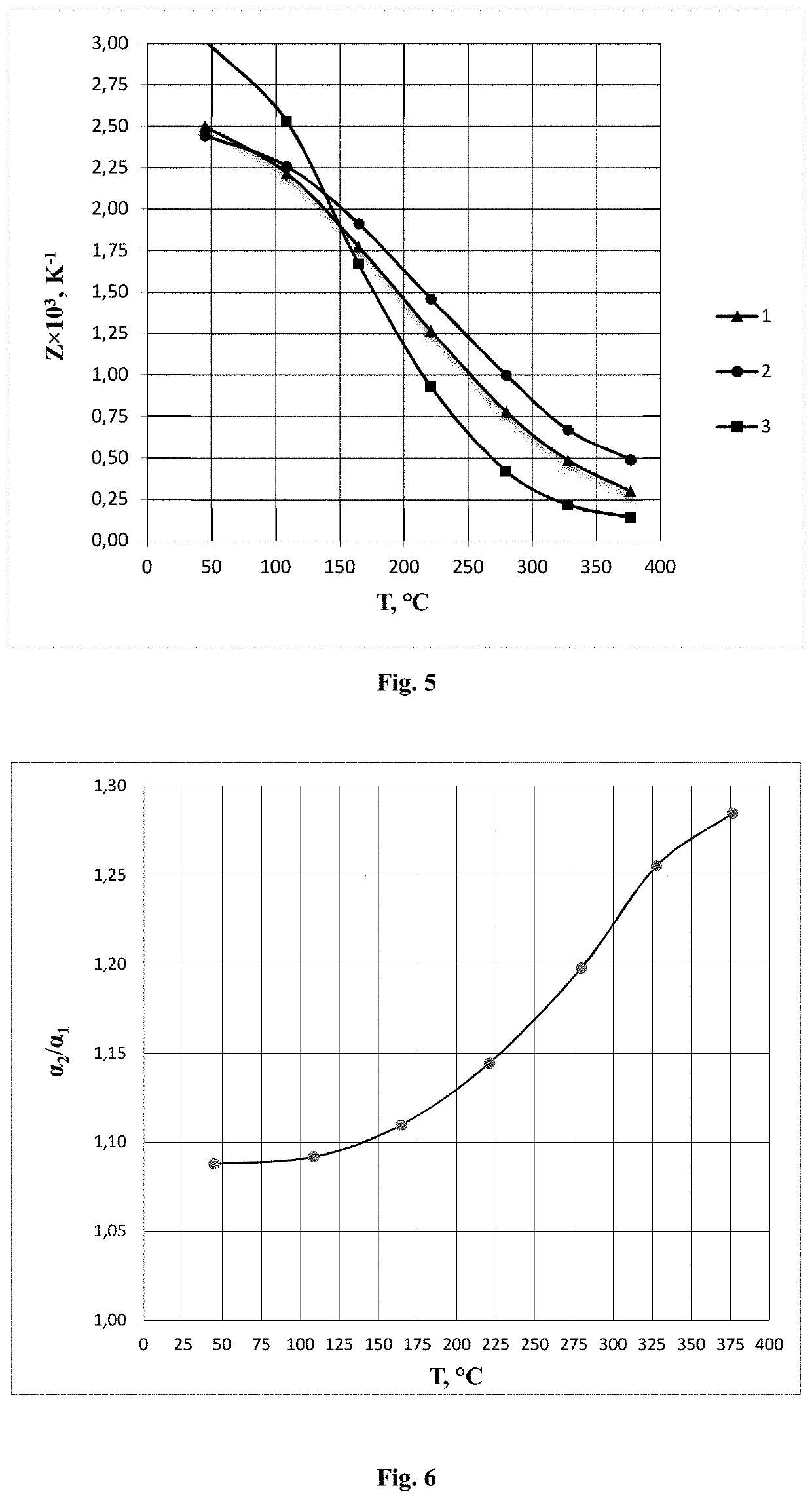
[0012]Improved thermoelectric efficiency of the thermoelectric element is achieved due to decrease in “negative” effect of minority charge carriers on the value of Seebeck coefficient and, accordingly, Z parameter. This is because Seebeck coefficient becomes anisotropic at elevated temperatures due to intensive thermal generation of minority charge carriers. Therefore, Seebeck coefficient value of p-type leg diced out transverse C axis (standard orientation) becomes less than Seebeck coefficient value of p-type leg diced out parallel C axis. As the result, at higher operating temperatures, maximum Z parameter values are observed in p-type leg diced out parallel C axis.

[0013]Materials for practical use in thermoelectric generation applications are always of polycrystalline or composite nature.

[0014]The main manufacturing technique of serial bulk materials based on Bi2Te3 and related alloys is powder compaction by hot pressing combined with Spark Plasma Sintering (SPS) or hot extrusi...

second embodiment

[0024]Therefore, to enhance significantly thermoelectric efficiency of thermoelectric element, we propose in second embodiment to manufacture thermoelectric element in which p-type leg is built of two parts diced out with different directions of axes in relation to C axis (see FIG. 9). Bottom part of the leg at cold end (low-temperature part) is diced out and positioned in thermoelectric element so that heat flow in it is directed perpendicular to C axis. Top part of the leg at hot end (high-temperature part) is diced out and positioned in thermoelectric element so that heat flow in it is directed parallel to C axis.


PUM


Abstract

The present invention relates to thermoelectric power generating devices using thermoelectric elements and thereby generating electricity realizing direct conversion of heat to electric power due to difference in temperature. The present invention is targeted on improving thermoelectric efficiency of a thermoelectric device. According to the first variant of the present invention, technical result is achieved by that a) in thermoelectric element consisting of p-type leg and n-type leg jointed in serial electrical circuit, p-type leg is made of polycrystalline textured semiconductor Bi2Te3—Sb2Te3 alloy with high thermoelectric efficiency in the operating temperature range T>100° C. and b) in p-type leg, heat flux is directed from the hot end to the cold end parallel the crystallographic axis C. According to the second variant of the present invention, technical result is achieved by that a) in thermoelectric element consisting of p-type leg and n-type leg jointed in serial electrical circuit, p-type leg is made of polycrystalline textured semiconductor Bi2Te3—Sb2Te3 alloy and built up of two parts which are in perfect electrical and thermal contact and b) in part of p-type leg at low-temperature end of thermoelectric element, heat flux is directed from the hot end to the cold end transverse the crystallographic axis C, while in part of p-type leg at high-temperature end of thermocouple, heat flux is directed from the hot end to the cold end parallel the crystallographic axis C.

Description

FIELD OF THE INVENTION[0001]The present invention relates to thermoelectric power generating devices using thermoelectric elements and thereby generating electricity realizing direct conversion of heat to electric power due to difference in temperature.BACKGROUND[0002]High-priority problem in thermoelectric power generation technology is improving thermoelectric efficiency of a thermoelectric device. That achieves by increasing thermoelectric efficiency of thermoelectric materials in a wide range of operating temperatures (from 50° C. to 350° C.) which represents by figure-of-merit of the material, or so-called Z parameter, defined as:Z=α2σκ,(1)where α is Seebeck coefficient, σ is electrical conductivity, and κ is thermal conductivity of thermoelectric material.[0003]A thermoelectric element consists of two legs made of p-type and n-type semiconductor materials (p-type and n-type legs, respectively) jointed to form a serial electrical circuit. Currently, ternary solid solutions (all...

Claims


Application Information

Patent Timeline
IPC IPC(8): H01L35/18H01L35/16
CPCH01L35/18H01L35/16H10N10/00H10N10/852H10N10/853
Inventor DASHEVSKY, ZINOVY MOISEEVICHDUDKIN, LEV DMITRIEVICHSKIPIDAROV, SERGEY YAKOVLEVICH
Owner OBSHCHESTVO S OGRANICHENNOJ OTVETSTVENNOSTYU RUSTEK
Learn More