Blower

Pending Publication Date: 2021-01-14
EMAK
View PDF0 Cites 2 Cited by
  • Summary
  • Abstract
  • Description
  • Claims
  • Application Information

AI Technical Summary

Benefits of technology

[0018]Thanks to such a solution further interface surfaces are avoided, which there would be in the case of two or more parts assembled together, which could make further discontinuities and thus cause further pressure losses along the conveying channel.
[0019]Yet another as

Problems solved by technology

Due to this coupling, the relative position between the two portions is not particularly stable, so that it may be the case that, due to the vibratio

Method used


Image

  • Blower
  • Blower
  • Blower

Examples


Embodiment Construction

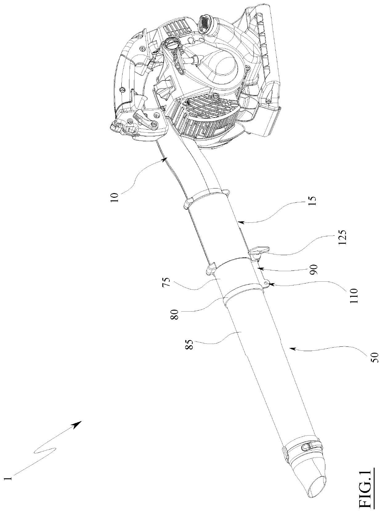
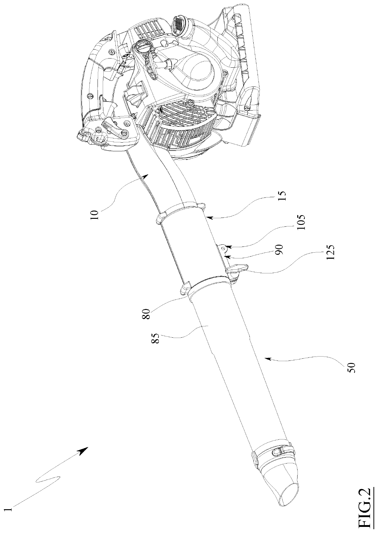
[0039]The present invention concerns a blower and, in particular, a blower equipped with a volute for conveying air.

[0040]The blower 1 firstly comprises an internal combustion engine and a tank for feeding the engine. This does not rule out the possibility that in other embodiments it can be an electric motor and that a suitable battery power pack is thus associated with it. The engine sets an impeller 5 in rotation, said impeller being shaped substantially like a fan. The impeller 5 is collected inside the conveying volute 10 and is adapted for putting the air in compression and conveying it through said volute.

[0041]The volute 10 can consist of an internally hollow body, for example a shell or casing, adapted for containing the impeller 5 and with which the impeller is rotatably associated with respect to a rotation axis.

[0042]The body of the volute 10 has, for example, two mutually opposite side flanks, a first flank of which can be constrained to the engine and to the respective...


PUM


Abstract

The invention describes a blower (1) comprising: a volute (10) for conveying air, a first tube (15) connected to the conveying volute (10), a second tube (50) adapted for being at least partially inserted in the first tube (15) and for sliding inside it along a sliding direction (A), and a fixing system of the second tube (50) to the first tube (15) in at least two positions, one of which is extracted and one is retracted.

Description

TECHNICAL FIELD[0001]The present invention concerns a blower and, in particular, a blower equipped with a volute for conveying air.STATE OF THE ART[0002]As known, a blower is a device capable of blowing and / or sucking and shredding leaves and other debris that is deposited day after day on lawns, flowerbeds, paths and surfaces in general.[0003]The blower generally comprises an internal combustion engine or electric motor, a lever or other element for selecting the power to be delivered, an impeller adapted for putting the air under pressure, a volute for conveying air and a tube for dispensing conveyed air.[0004]In some cases the dispensing tube is a telescopic tube, i.e. comprising two portions, of which a first portion is fixed to the volute for conveying air and a second portion can be made to slide inside the first portion and locked with respect to it in two or more positions through fixing systems generally based on the interference between suitable surfaces of the first porti...

Claims


Application Information

Patent Timeline
IPC IPC(8): A01G20/47
CPCA01G20/47
Inventor RIGHI, MATTEO
Owner EMAK
Why Eureka
Try Eureka