A method for obtaining 3-d deformity correction for bones

a 3-d deformation and bone technology, applied in the field of biomedical engineering, can solve problems such as orthogonal orientation of input images

Inactive Publication Date: 2021-01-14
KARADE VIKAS +1
View PDF18 Cites 7 Cited by
  • Summary
  • Abstract
  • Description
  • Claims
  • Application Information

AI Technical Summary

Benefits of technology

[0012]According to the prior art, the following steps refer to obtaining a method for obtaining ...

Problems solved by technology

A limitation of the prior art is that inp...

Method used


Image

  • A method for obtaining 3-d deformity correction for bones
  • A method for obtaining 3-d deformity correction for bones
  • A method for obtaining 3-d deformity correction for bones

Examples


example embodiment

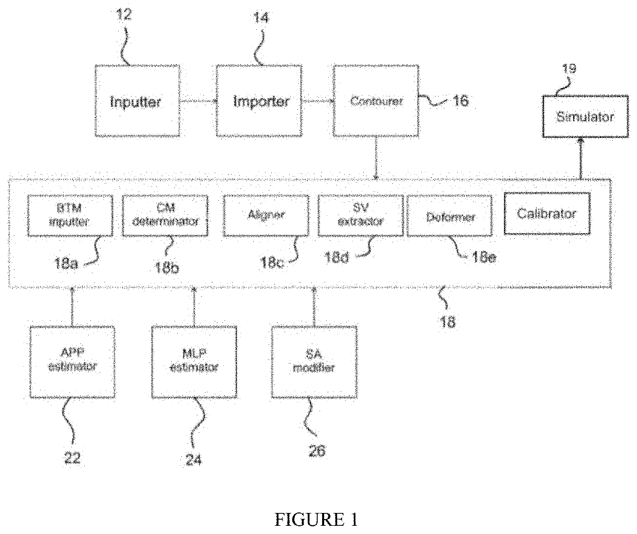
[0160 system 1 may include a medial-lateral pose estimator 24 configured to determine a second alignment of the template with respect to the input X-ray image, for a femur bone shape. Input to estimator 24 may be taken from contourer 16 which has contoured data and image of a bone's X-ray in its anterior-posterior view. An anterior-posterior projector projects the anterior-posterior image on to an image plane with arbitrary initial positions and orientation. This assists in formation of template models. The template model of femur, obtained from the bone template model input mechanism, is in the form of surface point cloud.

[0161]As shown in FIGS. 9 and 10, from the ML view X-ray image, separate boundary contours may be manually extracted for bone shaft, medial bone side, and lateral bone side. FIG. 9 illustrates template alignment with respect to Anterior-Posterior image and FIG. 10 illustrates template alignment with respect to Medial-Lateral image. The automatic initialization pro...


PUM


Abstract

A method for providing 3-dimensional deformity corrections for bones, said method comprising the steps of: acquiring an image of a bone of interest; acquiring contour points and landmark points, in a 2-dimensional co-ordinate system; obtaining a 3-dimensional deformed bone comprised in the foon of a mesh with mesh parameters; and obtaining initial anatomical regions, axes, landmarks, and parameters from said acquired contour points and landmark points; computing correction values and correction angles based on proximal anatomical axis (pSRL), distal anatomical axis (dSRL), proximal mechanical axis (pJRL), and/or distal mechanical axis (dJRL); applying torsional correction and/or angular correction based on said computed correction values, said computed correction angles, and pre-defined criteria; to obtain a simulated corrected bone model with at least one of corrected anatomical regions, landmarks, axes, and parameters, said correction being provided in terms of one of torsional and or bending deformity correction.

Description

FIELD OF THE INVENTION[0001]This invention relates to the field of biomedical engineering.[0002]Particularly, this invention to systems and methods for obtaining 3d deformity correction.BACKGROUND OF THE INVENTION[0003]Surgical planning is a preoperative method of visualising a surgical intervention, to set out the surgical steps and bone segment navigation in the context of computer assisted surgery. Surgical planning is important in orthopedic surgery, neurosurgery, oral and maxillofacial surgery, etc. Execution, or transfer of the surgical planning to the patient, is generally performed with a medical navigation system.[0004]Some orthopedic surgeries, like knee or hip replacement, and complex bone deformity corrections, include cutting or drilling on an irregular-shaped a bone. Performance and accuracy of such surgeries improves if the surgery is planned pre-operatively. Surgeons are trained to use conventional 2D image data to prepare for their complex procedures. Such planning ...

Claims


Application Information

Patent Timeline
IPC IPC(8): A61B34/10G06T7/149G06T17/20G06T3/40G06T11/00
CPCA61B34/10G06T7/149G06T17/205G06T3/40A61B2034/105G06T11/005G06T2207/30008G06T2207/20101G06T2207/10081G06T11/006G06T19/20G06T2219/2021G06T2210/41
Inventor KARADE, VIKASMAURYA, AMIT
Owner KARADE VIKAS
Why Eureka
Try Eureka