
Thermoplastic Composite Product

a technology of thermoplastic composite products and thermoplastic materials, which is applied in the field of manufacturing thermoplastic composite products, can solve the problems of reducing the strength between and the opposing fiber layers in the first and second components do not sufficiently cooperate to transfer forces from one component to another, so as to reduce the amount of thermoplastic materials and improve the strength of connection

Active Publication Date: 2021-01-14
DUTCH THERMOPLASTIC COMPONENTS BV
View PDF0 Cites 0 Cited by
  • Summary
  • Abstract
  • Description
  • Claims
  • Application Information

AI Technical Summary

Benefits of technology

The invention provides a method for making a stepped structure by stacking plies of thermoplastic material on top of each other and connecting them using laser beam processing. This method avoids the use of a laser beam to generate ply drop offs, which reduces the amount of material on the surface of the stepped structure and may result in a degradation of the strength of the connection between components. The method allows for accurate positioning of the plies and can involve using local fixation, such as ultrasonic welding or tack welding, to prevent movement of the plies during processing. Alignment of the first and second components during the heating of the ply drop offs can also be achieved using clamping or other means. The technical effects of this invention include improved strength of the stepped structure and more precise positioning of the plies.

Problems solved by technology

The Applicant has found that a cause for the abovementioned problem of reduced strength between the first and second components can be attributed to misalignment between the fiber layers of the first and second components.
More in particular, opposing fiber layers in the first and second components do not sufficiently cooperate to transfer forces from one component to the other.

Method used


Image

  • Thermoplastic Composite Product
  • Thermoplastic Composite Product
  • Thermoplastic Composite Product

Examples


Embodiment Construction

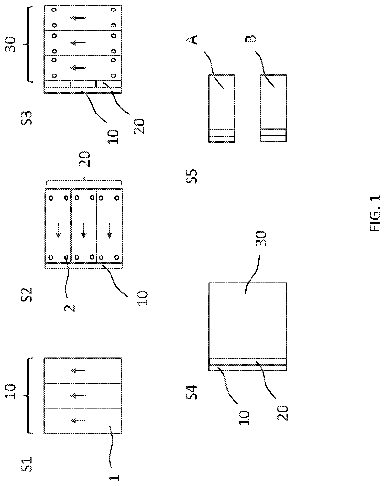
[0055]FIG. 1 illustrates a method for manufacturing a first and second thermoplastic composite component having a ply drop off in accordance with the invention. As a first step S1, a plurality of unidirectional thermoplastic composite plies 1 is arranged with the orientation of the plies, indicated by the arrows in the figure, being identical. In FIG. 1, plies 1 are identical and comprise aligned reinforcing fibers that are encapsulated by a thermoplastic material. Together, plies 1 form a first layer 10. Plies 1 can be arranged on a table using a suitable robotic arm or may be arranged manually. In addition, plies 1 may be mutually fixated, e.g. using tack welding such as ultrasonic welding.

[0056]As a second step S2, another layer of plies 1 is arranged on top of plies 1 that were already placed albeit using a different orientation, e.g. 90 degrees difference. Together, plies 1 form a second layer 20. This process is repeated in a third step S3 for the formation of a third layer 30...


PUM

PropertyMeasurementUnit
Lengthaaaaaaaaaa
Temperatureaaaaaaaaaa
Pressureaaaaaaaaaa

Abstract

A method for manufacturing a thermoplastic composite product includes: providing a first and second thermoplastic composite component made from a consolidated stack of thermoplastic composite plies, said first and second component having a first and second ply drop off, respectively. The first and second components are positioned such that the first ply drop off and the second ply drop off are aligned, and the first and second components are fixedly connected by means of heating. The stacks of plies for the first and second components are constructed by stacking the plies in a stacking direction wherein the plies are arranged such that plies at a different position along the stacking direction are laterally offset relative to each other for the purpose of forming the first ply drop off and the second ply drop off, respectively, before consolidating.

Description

CROSS-REFERENCE TO RELATED APPLICATIONS[0001]This application claims priority to Netherlands patent application serial number NL2023482, filed Jul. 11, 2019, the entirety of which application is incorporated by reference herein.FIELD OF THE DISCLOSURE[0002]The present invention relates to a method for manufacturing a thermoplastic composite product. The present invention further relates to a method for connecting a first thermoplastic composite component having a first connecting region and being made from a consolidated stack of thermoplastic composite plies to a second thermoplastic composite component having a second connecting region and being made from a consolidated stack of thermoplastic composite plies. In addition, the present invention relates to a thermoplastic composite product and to a structural component of an aircraft comprising the same.BACKGROUND[0003]Thermoplastic composites consist of a thermoplastic matrix combined with a reinforcing material typically in the fo...

Claims


Application Information

Patent Timeline
IPC IPC(8): B29C65/00B29C65/18
CPCB29C66/12822B29C66/12842B29K2995/0051B29C66/72141B29C66/723B29C65/18B29C66/721B29C66/14B29C66/43B29C66/73921B29C65/08B29C66/1162B29C66/91423B29C66/3472B29C66/91933B29C66/91935B29C66/81811B29C66/21B29C66/7212B29C66/71B29C66/348B29C66/0246B29C66/83221B29L2031/3076B29C70/304B29K2309/08B29K2277/10B29K2309/04B29K2307/04B29K2023/00B29K2077/00B29K2079/085B29K2081/04B29K2071/00B29C66/12841B29C66/128
Inventor MANTEN, DAVID REIJERVROEMEN, JEFFREY ROGIERLUNENBORG, DENNISBOER, PETER FLORIS EVERT
Owner DUTCH THERMOPLASTIC COMPONENTS BV
Learn More