Magnetic memory and method for controlling the same

a technology of magnetic memory and control method, applied in the direction of digital storage, galvano-magnetic material selection, instruments, etc., can solve the problem that the magnetoresistance effect element will have a long life, and achieve the effect of improving integration characteristics

Active Publication Date: 2021-01-14
TDK CORPARATION
View PDF0 Cites 2 Cited by
  • Summary
  • Abstract
  • Description
  • Claims
  • Application Information

AI Technical Summary

Benefits of technology

[0010]The present disclosure has been made in view of the above circumstances and provides a magnetic memory which is able to enhance integration characteristics.
[0027]The magnetic memory according to the present embodiment can improve integration characteristics.

Problems solved by technology

It is not necessary to cause a current to flow in the laminating direction of the magnetoresistance effect element, and it is expected that such a magnetoresistance effect element will have a long lifespan.

Method used


Image

  • Magnetic memory and method for controlling the same
  • Magnetic memory and method for controlling the same
  • Magnetic memory and method for controlling the same

Examples


first embodiment

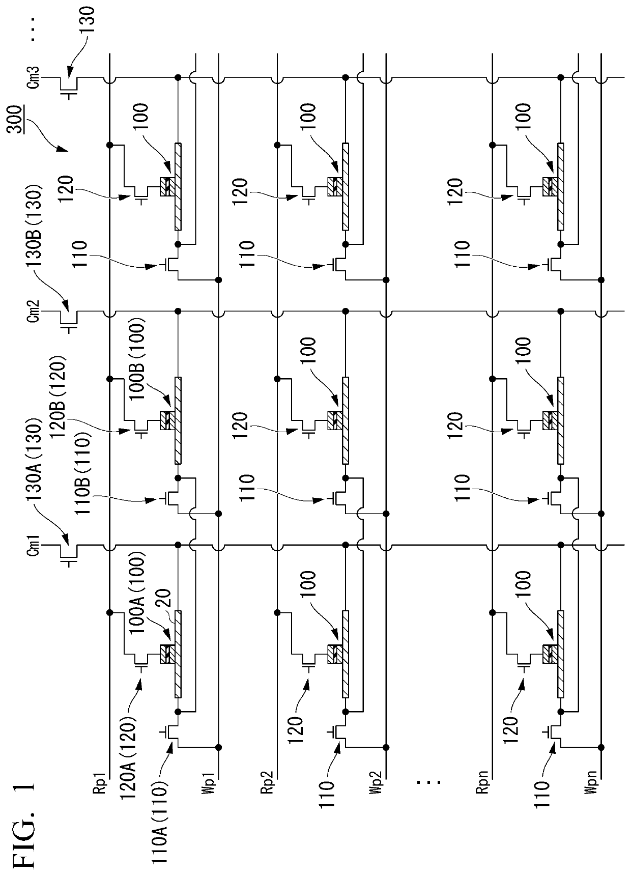
[0054]FIG. 1 is a view schematically illustrating an example of constitution of a magnetic memory 300 according to a first embodiment. The magnetic memory 300 includes a plurality of storage elements 100, a plurality of write wirings Wp1 to Wpn, a plurality of common wirings Cm1 to Cmn, a plurality of read wirings Rp1 to Rpn, a plurality of first switching elements 110, a plurality of second switching elements 120, and a plurality of third switching elements 130. The magnetic memory 300 may be referred to as a magnetic recording array, and the storage element 100 may be referred to as a recording element, a magnetic element, or a spin element.

[0055]The write wirings Wp1 to Wpn electrically connect a power supply to one or more storage elements 100. The write wirings Wp1 to Wpn are wirings used when data is written in the storage element 100. The read wirings Rp1 to Rpn electrically connect the power supply to one or more storage elements 100. The read wirings Rp1 to Rpn are wirings ...

second embodiment

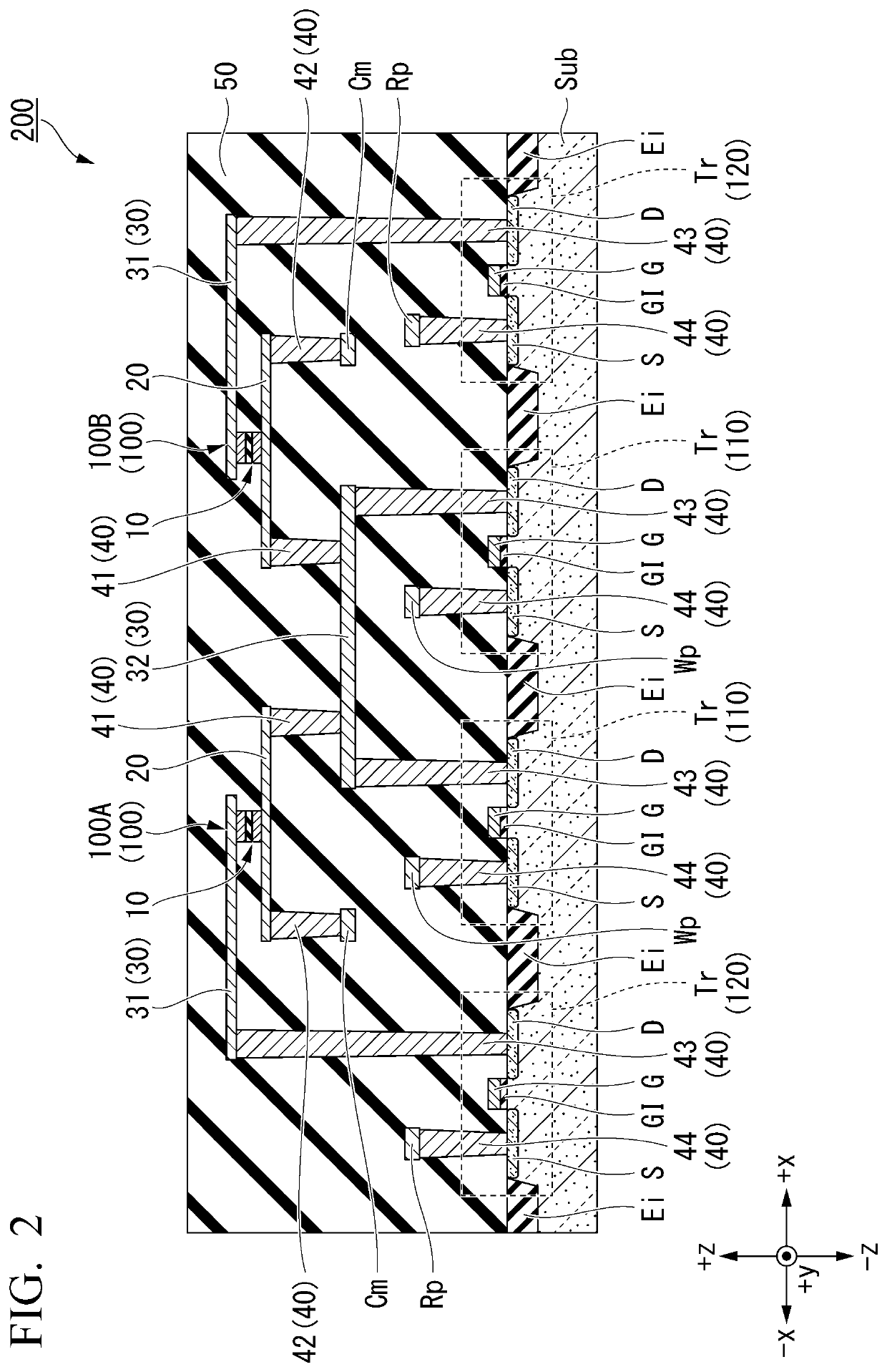
[0108]FIG. 9 is a view schematically illustrating an example of constitution of a magnetic memory 301 according to a second embodiment. FIG. 10 is a cross-sectional view of a main part (a semiconductor device 201) of the magnetic memory 301 according to the second embodiment. FIG. 10 is a cross section of the storage element 100 taken along the xz plane which passes through a center of the width of the first conductive layer 20 in the y direction. The magnetic memory 301 according to the second embodiment is different from the magnetic memory 300 according to the first embodiment in that the second switching element 120 is connected over the plurality of storage elements 100, and the third switching element 130 is connected to each of the plurality of storage elements 100. The other constitutions are the same as those of the magnetic memory 300 according to the first embodiment, and the description thereof will be omitted.

[0109]In FIG. 9, the first switching element 110 and the thir...

third embodiment

[0115]FIG. 14 is a view schematically illustrating an example of constitution of a magnetic memory 302 according to a third embodiment. FIG. 15 is a cross-sectional view of a main part (a semiconductor device 202) of the magnetic memory 302 according to the third embodiment. FIG. 15 is a cross section of the storage element 100 taken along the xz plane which passes through the center of the width of the first conductive layer 20 in the y direction. The magnetic memory 302 according to the third embodiment is different from the magnetic memory 300 according to the first embodiment in that it has a rectifier 140. The other constitutions are the same as those of the magnetic memory 300 according to the first embodiment, and the description thereof will be omitted.

[0116]The rectifier 140 is provided in the common wirings Cm1 to Cmn connected to the third switching element 130 in FIG. 14. The third switching element 130 in FIG. 14 is an example of a common switching element. The common w...


PUM

PropertyMeasurementUnit
timeaaaaaaaaaa
atomic numberaaaaaaaaaa
time taaaaaaaaaaa

Abstract

A magnetic memory includes a storage element including a first ferromagnetic layer, a first conductive layer which faces the first ferromagnetic layer in a first direction and extends in a second direction different from the first direction, and a first conductive part and a second conductive part which are connected to the first conductive layer at positions which sandwich the first ferromagnetic layer in the second direction when seen in the first direction; and a plurality of first switching elements which are electrically connected to the first conductive part of the storage element.

Description

BACKGROUND OF THE INVENTIONField of the Invention[0001]The present disclosure relates to a magnetic memory and a method for controlling the same.[0002]Priority is claimed on Japanese Patent Application No. 2019-128453, filed Jul. 10, 2019, the content of which is incorporated herein by reference.Description of Related Art[0003]A giant magnetoresistance (GMR) element including a multilayer film of a ferromagnetic layer and a nonmagnetic layer, a tunneling magnetoresistance (TMR) element using an insulating layer (a tunnel barrier layer, a barrier layer) for an nonmagnetic layer, and the like are known as an element which utilizes a change in a resistance value (a change in magnetoresistance) based on a change in an relative angle of magnetization between two ferromagnetic layers.[0004]In recent years, attention has been focused on an element using a spin orbit torque (SOT) and an element using a displacement of a magnetic domain wall among spin elements using a change in magnetoresis...

Claims


Application Information

Patent Timeline
Patent Type & Authority Applications(United States)
IPC IPC(8): G11C11/16H01L43/08H01L43/10H01L43/04
CPCG11C11/161H01L43/04H01L43/10H01L43/08G11C11/1693G11C11/1657G11C11/1673G11C11/1675H10B61/22H10N50/80H10N50/10H10N50/85H10N52/80
Inventor SHIOKAWA, YOHEI
Owner TDK CORPARATION
Why Eureka
Try Eureka