Method of modeling fluid flow downhole and related apparatus and systems

a technology of fluid flow and modeling method, applied in the field of earth-moving operations, can solve problems such as formation, drill string sticking in the borehole, and problems that may develop throughout the wellbor

Pending Publication Date: 2021-01-21
BAKER HUGHES OILFIELD OPERATIONS LLC
View PDF3 Cites 10 Cited by
  • Summary
  • Abstract
  • Description
  • Claims
  • Application Information

AI Technical Summary

Benefits of technology

[0004]Some embodiments may include an earth-boring system for generating a fluid flow model of a borehole. The earth-boring system may include a drill string and a model generation system. The drill string may include at least one drilling tool. The model generation system may include at least one processor and a memory device. The memory device may store data representative of a plurality of mathematical simulations of a borehole. The processor may include at least one non-transitory computer-readable storage medium storing instructions. The instruction may cause the model generation system to receive real-time operational data from the drill string representing real-time operational parameters of the drill string, the operational parameters comprising set-points, acceptable ranges, operational limitations, and real-time data. The instructions may also cause the model generation system to analyze the operational parameters via one or more of the plurality of mathematical simulations, the plurality of mathematical simulations being determined from a set of generic operating parameters, and each mathematical simulation being determined at least in part by a unique parameter relative to other mathematical simulations in the plurality of mathematical simulations. The instructions may further cause the model generation system to identify a mathematical simulation from the plurality of mathematical simulations that most closely matches the real-time data and meets the set-points, the acceptable ranges, and the operational limitations. The instructions may also cause the model generation system to generate a simplified mathematical fluid flow model utilizing both the mathematical simulation and the real-time operational data.

Problems solved by technology

Problems may develop throughout the wellbore if the operational properties of the drilling fluid are not appropriate for accomplishing the act that the fluid is meant to perform.
For example, if the flow rate is not sufficient to maintain drill cuttings suspended within the fluid the cuttings may settle or accumulate within the borehole forming cutting beds that can obstruct fluid flow and / or restrict movement of the drill string potentially causing the drill string to stick in the borehole.
On the other hand, if the flow rate and / or pressure is too high additional undesired erosion of the formation may occur as the fluid flows upward through the wellbore.
The undesired erosion may result in an unstable borehole that could result in cave-ins and / or stuck drill strings or pipes.
A stuck drill string or pipe may result in significant amounts of lost time and money while the situation is remedied.

Method used


Image

  • Method of modeling fluid flow downhole and related apparatus and systems
  • Method of modeling fluid flow downhole and related apparatus and systems
  • Method of modeling fluid flow downhole and related apparatus and systems

Examples


Embodiment Construction

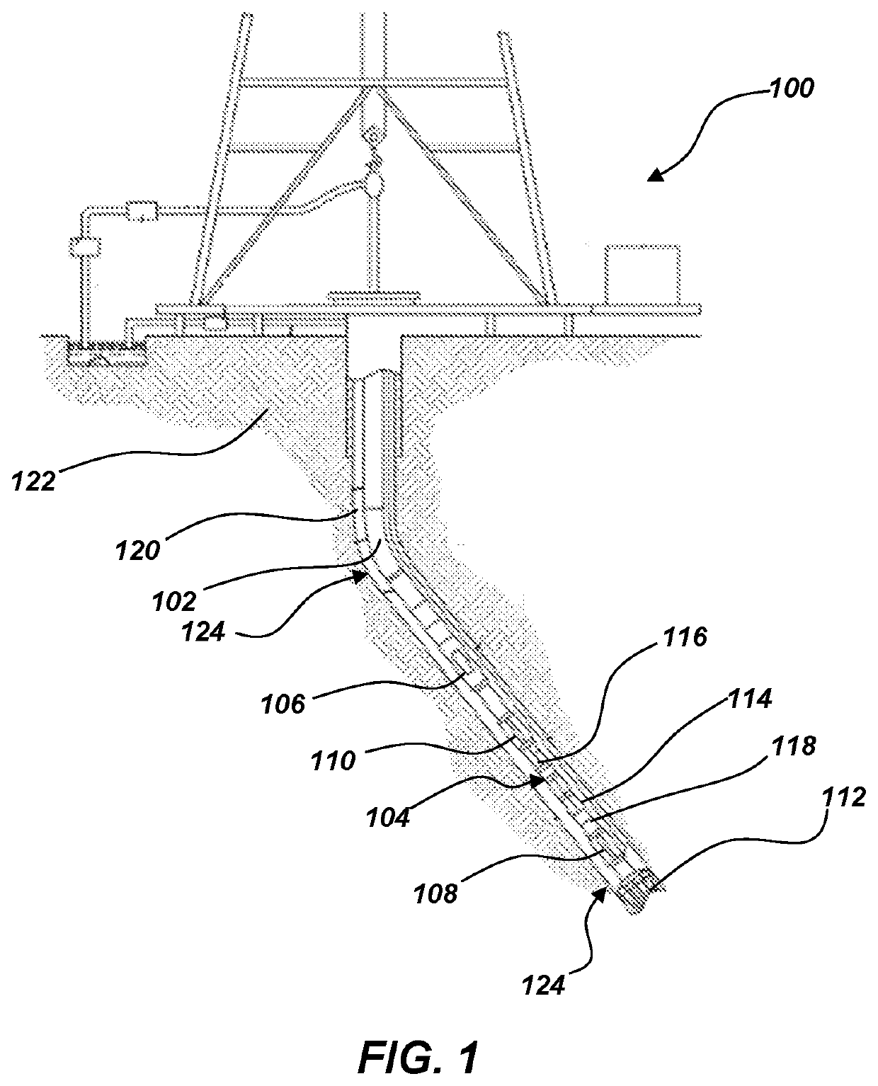
[0011]The illustrations presented herein are not meant to be actual views of any particular earth-boring system or component thereof, but are merely idealized representations employed to describe illustrative embodiments. The drawings are not necessarily to scale.

[0012]As used herein, the term “substantially” in reference to a given parameter means and includes to a degree that one skilled in the art would understand that the given parameter, property, or condition is met with a small degree of variance, such as within acceptable manufacturing tolerances. For example, a parameter that is substantially met may be at least about 90% met, at least about 95% met, at least about 99% met, or even at least about 100% met.

[0013]As used herein, relational terms, such as “first,”“second,”“top,”“bottom,” etc., are generally used for clarity and convenience in understanding the disclosure and accompanying drawings and do not connote or depend on any specific preference, orientation, or order, e...


PUM


Abstract

An earth-boring system for generating a fluid flow model of a borehole may include a drill string, and a model generation system. The model generation system may include a memory device and a processor. The memory device may store a plurality of mathematical simulations of a borehole. The processor may receive real-time operational data, analyze the real-time operational data via one or more of the mathematical simulations, identify a mathematical simulation that most closely matches the real-time operational data, and generate a simplified mathematical fluid flow model utilizing both the mathematical simulation and the real-time operational data.

Description

TECHNICAL FIELD[0001]Embodiments of the present disclosure generally relate to earth-boring operations. In particular, embodiments of the present disclosure relate to methods of modeling fluid flow downhole and related apparatus and systems.BACKGROUND[0002]During the drilling of a wellbore, various fluids are typically used in the well for a variety of functions. The fluids may be circulated through a string of drill pipe and a drill bit into the wellbore and, then, may subsequently flow upward through a wellbore annulus surrounding the drill string to the surface. During this circulation, the drilling fluid may act to remove cuttings of formation material being drilled from the bottom of the wellbore to the surface. The drilling fluid may also suspend formation cuttings and weighting material (i.e., solids in the drilling fluid) when circulation is interrupted. The drilling fluid may be used to control subsurface pressures and / or to maintain the integrity of the wellbore until the ...

Claims


Application Information

Patent Timeline
Patent Type & Authority Applications(United States)
IPC IPC(8): E21B44/02E21B21/08E21B47/12E21B41/00
CPCE21B44/02E21B41/0092E21B47/124E21B21/08G06F30/28G06F2113/08G06F2119/14E21B2200/20E21B44/06G06N20/00E21B47/26
Inventor ARAGALL, ROGERMAY, ROLANDDAHL, THOMASOSGOUEI, REZA ETTEHADIIGNATENKO, YAROSLAV SERGEYEVICH
Owner BAKER HUGHES OILFIELD OPERATIONS LLC
Why Eureka
Try Eureka