Optimized thread profile for joining composite materials

Active Publication Date: 2021-01-21
SHERLIN DENNIS
View PDF0 Cites 0 Cited by
  • Summary
  • Abstract
  • Description
  • Claims
  • Application Information

AI Technical Summary

Problems solved by technology

This thread cutting process weakens the co

Method used


Image

  • Optimized thread profile for joining composite materials
  • Optimized thread profile for joining composite materials
  • Optimized thread profile for joining composite materials

Examples


Embodiment Construction

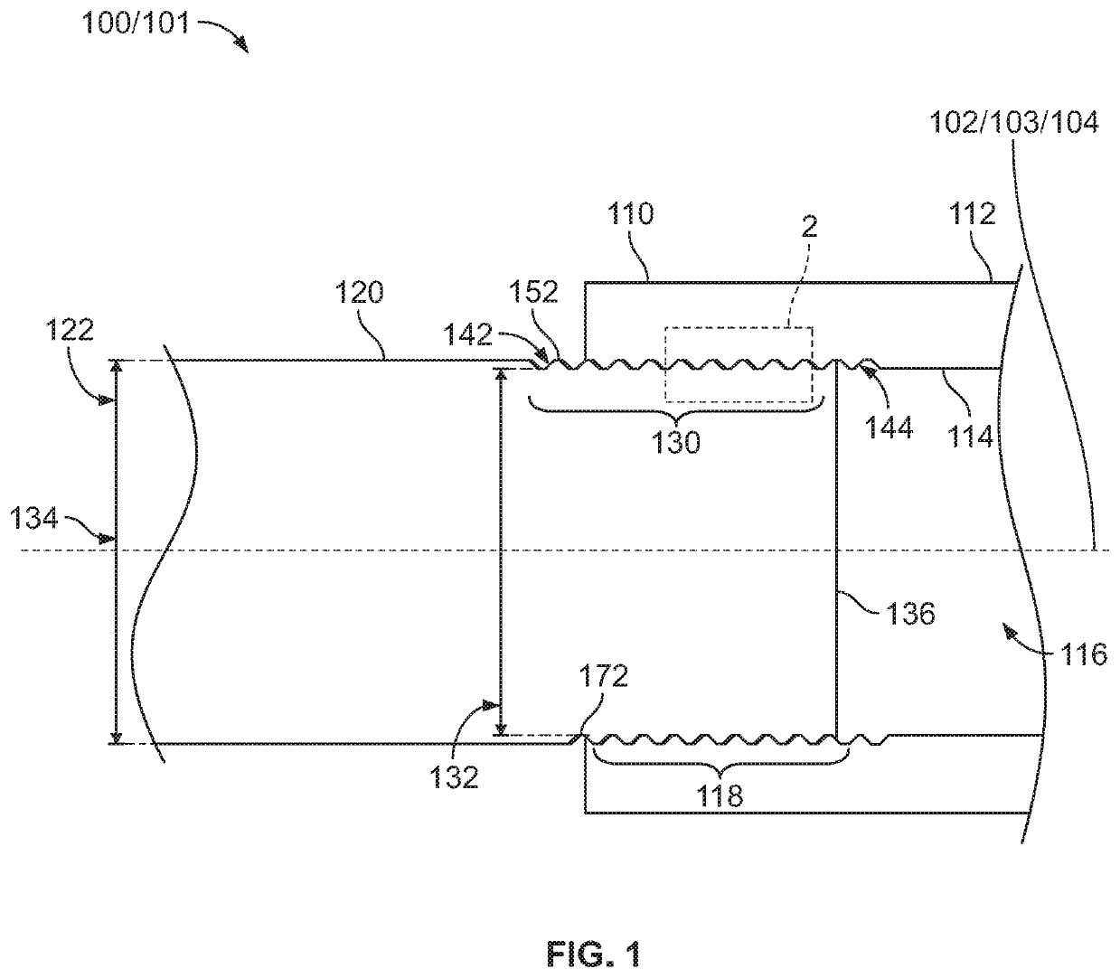
[0019]A threaded joint (100) is comprised of a shaft (120) and a joining shaft (110). When the shaft (120) and the joining shaft (110) are made from composite materials, it is called a composite threaded joint (101). The shaft (120) is joined to the joining shaft (110) by affixing the shaft (120) with a male thread (142) into the joining shaft (110) with a female thread (144).

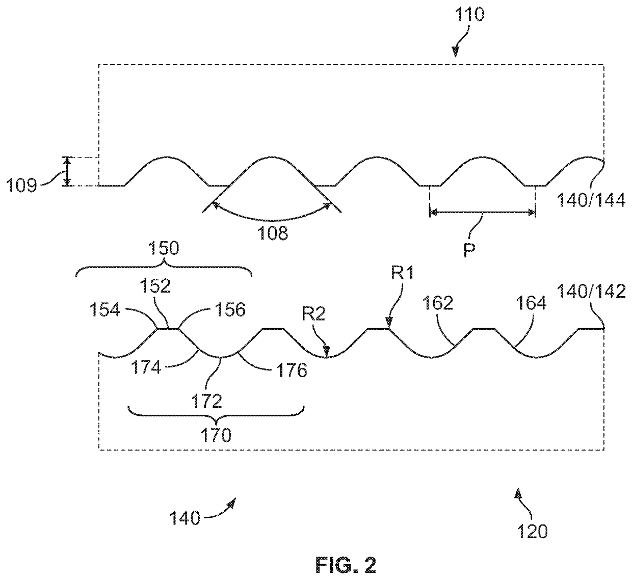
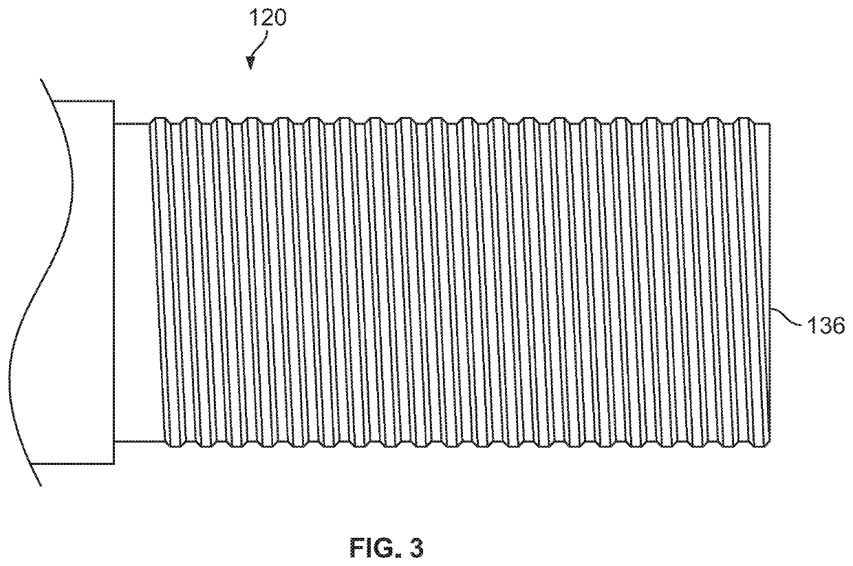
[0020]The shaft (120) has a threaded portion (130). At least one of the ends (136) of the threaded portion (130) has a flat profile, perpendicular to the central axis (102) of the shaft (120)(See FIG. 1).

[0021]The joining shaft (110) is a tubular sleeve comprising an exterior surface (112) and an interior surface (114), the interior surface (114) defining a sleeve bore (116). The interior surface (114) has a threaded portion (118). The sleeve bore (116) has a threaded portion (118), which is the mirror image of the threaded portion (118) of the interior surface (114).

[0022]The threaded portion (130) of the shaf...


PUM

PropertyMeasurementUnit
Angleaaaaaaaaaa
Angleaaaaaaaaaa
Angleaaaaaaaaaa

Abstract

An optimized thread profile (140) for joining composite materials is presented. This thread profile (140) maintains a certain material strength when used as part of a composite threaded joint (101). The thread profile (140) comprises a repeating pattern of four components: a crest region (150), a first flank (162), a root region (170) and a second flank (164). The thread profile (140) is symmetrical, that is, the dimensions of the four components do not change throughout the length of the thread profile. The crest (152) has a flat profile and the root (172) has a rounded profile. When a shaft (120) is affixed to a joining shaft (110) using this optimized thread profile (140), the flat profiles of the crest (152) of the shaft (120) and corresponding rounded profiles of the root (172) of the joining shaft (110) create a gap to accommodate a substance such as an adhesive or a lubricant. Similarly, the flat profiles of the crest (152) of the joining shaft (110) and corresponding rounded profiles of the root (172) of the shaft (120) create a gap to accommodate a substance.

Description

CROSS-REFERENCE TO RELATED APPLICATIONS[0001]This application claims the priority benefit of U.S. Provisional Patent Application Ser. No. 62 / 874,517 filed Jul. 16, 2019, whose entire disclosure is expressly incorporated by reference in its entirety herein.STATEMENT REGARDING FEDERALLY SPONSORED RESEARCH OR DEVELOPMENT[0002]Not ApplicableTHE NAMES OF THE PARTIES TO A JOINT RESEARCH AGREEMENT[0003]Not ApplicableREFERENCE TO A “SEQUENCE LISTING,” A TABLE, OR A COM-PUTER PROGRAM[0004]Not ApplicableSTATEMENT REGARDING PRIOR DISCLOSURES BY AN INVENTOR OR JOINT INVENTOR[0005]Not ApplicableBACKGROUND OF THE INVENTIONField of Invention[0006]The present invention generally relates to threaded joints made from composite materials.Description of Related Art[0007]Composite materials contain a fiber material bound together with a matrix, most often a polymer such resin or a plastic material. Fiber is used to add strength to the composite. Placing fiber in various directions allows the designer to...

Claims


Application Information

Patent Timeline
IPC IPC(8): F16B39/22B29C65/48
CPCF16B39/225B29C65/48B29C65/561B29C66/5221B29C66/1122B29C66/71B29C66/7212F16L15/06B29C66/526F16B33/006B29K2063/00B29K2309/08F16B39/22
Inventor SHOOK, ADAM R
Owner SHERLIN DENNIS
Why Eureka
Try Eureka