Lens assembly

a technology of lens assembly and lens drive device, which is applied in the direction of camera focusing arrangement, printers, instruments, etc., can solve the problems of adversely affecting image quality or resolution, increase of power consumption or control characteristics, and reduce drive force, so as to improve control characteristics, reduce power consumption, and improve driving force

Pending Publication Date: 2021-01-21
LG INNOTEK CO LTD
View PDF3 Cites 4 Cited by
  • Summary
  • Abstract
  • Description
  • Claims
  • Application Information

AI Technical Summary

Benefits of technology

[0049]The lens assembly, the lens driving device, and the camera module including the same according to the embodiment have a technical effect capable of solving the problem of generating a friction torque during zooming.
[0050]For example, according to the embodiment, there are technical effects such as improvement of driving force, reduction of power consumption, and improvement of control characteristics by preventing occurrence of friction torque during zooming.
[0051]In addition, according to the embodiment, there is a technical effect of solving the problem of occurrence of lens decenter or lens tilt during zooming.
[0052]For example, according to the embodiment, when zooming, the tolerance of the moving contact part is significantly reduced, thereby minimizing friction torque, while preventing the occurrence of lens decent or lens tilt, significantly improving image quality or resolution.
[0053]In addition, according to the embodiment, there is a technical effect that the zooming function can be smoothly performed even in a compact camera module.
[0054]For example, according to an embodiment, a compact camera module can be implemented by arranging a position sensor and a hall sensor in one stroke section to reduce an area occupied by the position sensor.

Problems solved by technology

On the other hand, friction torque is being generated during lens movement using lens driving device for zooming function in camera module, and this friction torque is causing technical problems such as reduction of drive force, increase of power consumption or deterioration of control characteristics.
However, if a decent or tilt occurs, which causes the center of the spherical surface between lenses to deviate from the optical axis, the angle of picture changes or deviates from focus, which adversely affects image quality or resolution.
On the other hand, in the case of increasing the separation in the moving area to reduce frictional torque resistance when moving the lens for the zooming function in the camera module, there is technical contradiction in that the lens decent or lens tilting arises while zoom moving or reversing of the zoom movement.
In addition, there is a problem in that it is difficult to implement a zooming function applied in a general large camera because there is a space limitation for zooming because the compact camera module has a size limitation.
In addition, although it is important to sense the position of the lens that is moved during zooming in the camera module, there is a technical problem in that the reliability of measuring the position of the lens that is moved during zooming is lowered in the related art.

Method used


Image

  • Lens assembly
  • Lens assembly
  • Lens assembly

Examples


example

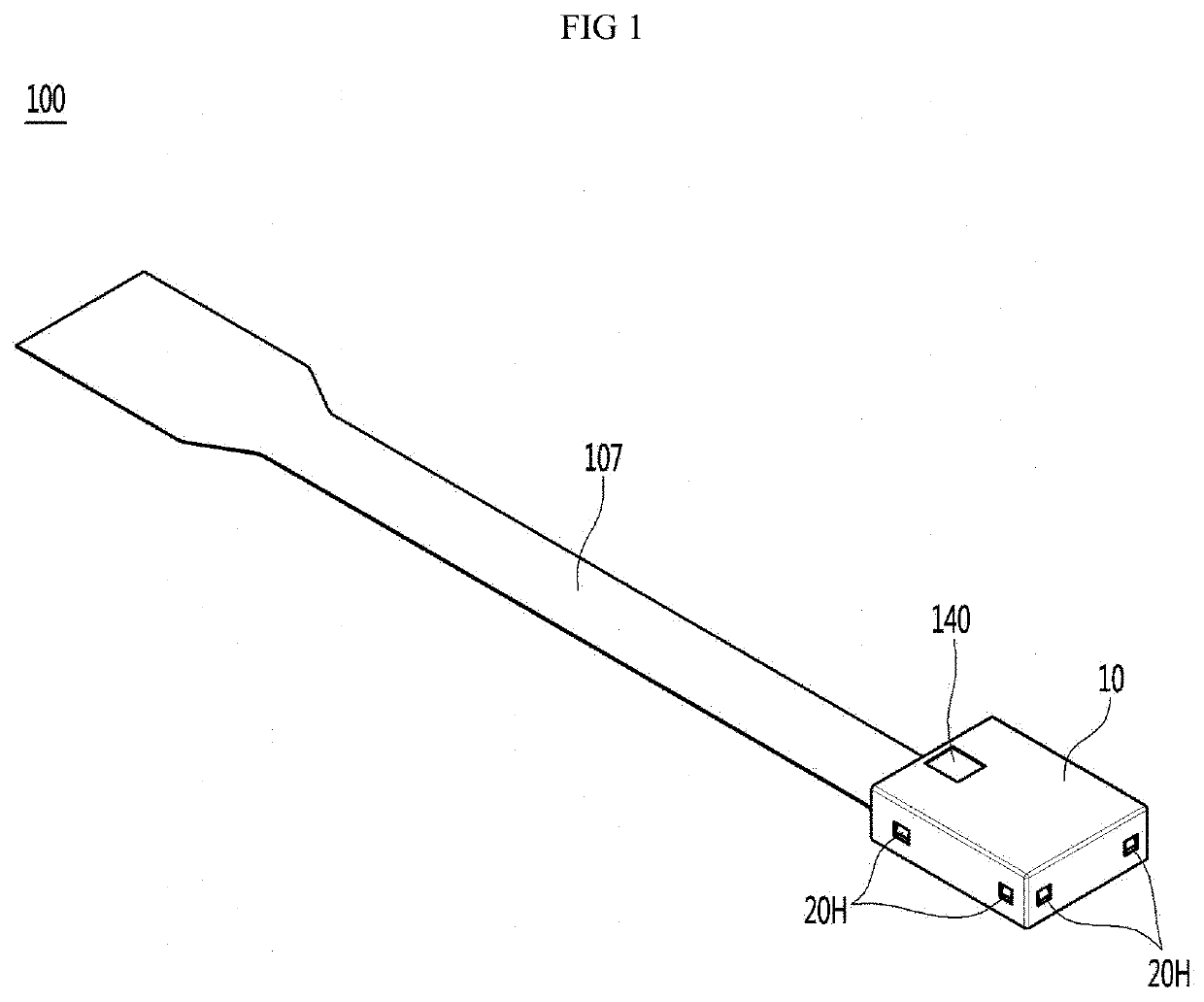
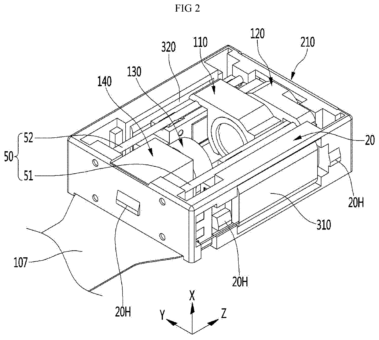
[0088]FIG. 1 is a perspective view of a camera module 100 according to an embodiment, and FIG. 2 is a perspective view with a cover 10 removed from the camera module 100 according to the embodiment shown in FIG. 1.

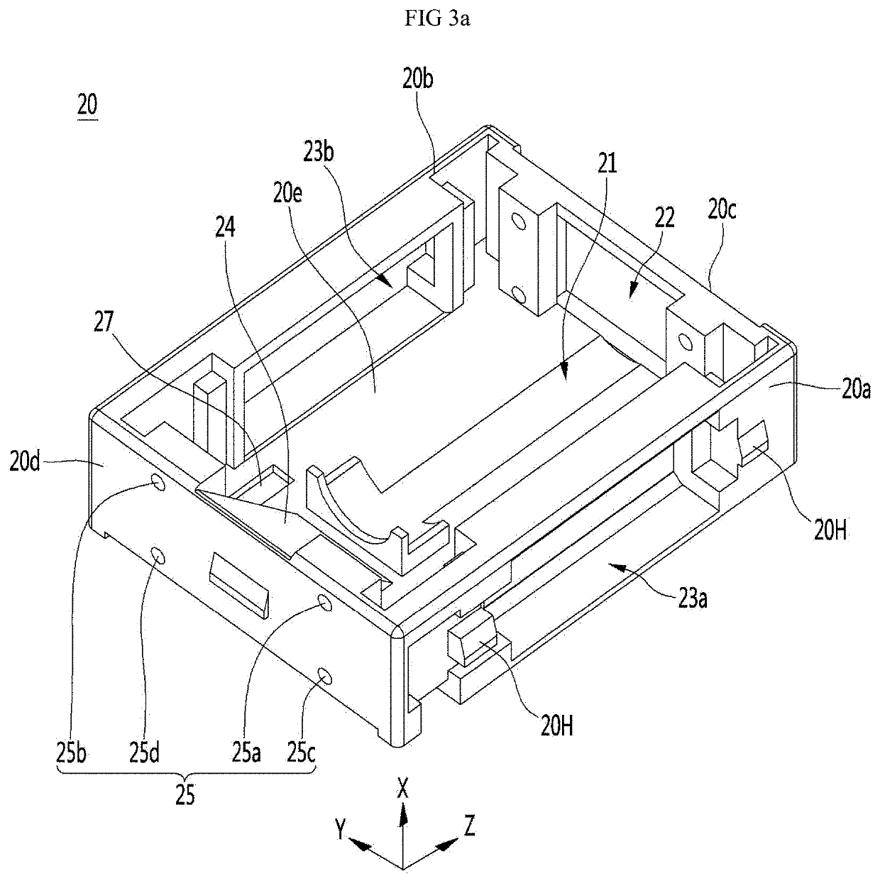
[0089]First, referring mainly to FIG. 1, in the camera module 100 according to the embodiment, various optical systems, for example, a prism 140 and a lens group are disposed on a predetermined case 20 (see FIG. 2), and the cover 10 is coupled through a hook 20H of case 20. The case 20 may also be referred to as a mount.

[0090]The cover 10 is coupled to the case 20 and covers a component accommodated in the case 20 to protect the components of the camera module. The case 20 may be referred to as a base.

[0091]The cover 10 may be fitted with the case 20 in shape, or may be coupled by an adhesive. For example, a hook 20H may protrude from the side of the case 20, and the cover 10 has a hole formed at a position corresponding to the hook H, and the hook of the case 20 is mounte...


PUM


Abstract

Embodiments relate to a lens assembly, a lens driving apparatus, and a camera module comprising same. A lens assembly according to an embodiment may comprise: a first pin; a first housing which moves along the first pin; a first lens group arranged in the first housing; and a first wheel which is arranged in the first housing and moves along the first pin. The first wheel may include a first rotation shaft coupled to the first housing, and a first rotation part which rotates about the first rotation shaft. The first rotation part may include a groove corresponding to the first pin, wherein the maximum depth of the groove may be less than one-half the maximum thickness of the first pin in a direction perpendicular to the first rotation shaft.

Description

TECHNICAL FIELD[0001]The embodiment relates to a lens assembly, a lens driving device, and a camera module including the same.BACKGROUND ART[0002]The camera module performs a function of photographing a subject and storing it as an image or video, and is installed in mobile terminals such as mobile phones, laptops, drones, and vehicles.[0003]On the other hand, portable devices such as smartphones, tablet PCs, and laptops have built-in ultra-small camera modules, and these camera modules automatically adjust the distance between the image sensor and the lens to align the focal length of the lens with an autofocus function.[0004]Recently, a camera module may perform a zooming function of zooming up or zooming out of photographing by increasing or decreasing the magnification of a distant subject through a zoom lens.[0005]On the other hand, friction torque is being generated during lens movement using lens driving device for zooming function in camera module, and this friction torque i...

Claims


Application Information

Patent Timeline
Patent Type & Authority Applications(United States)
IPC IPC(8): G02B7/09G02B7/10G03B13/36G03B5/00
CPCG02B7/09G02B7/10G02B13/18G03B5/00G03B2205/0046G03B13/36G03B30/00G03B3/10G03B2205/0053
Inventor PARK, SUNG JUNE
Owner LG INNOTEK CO LTD
Why Eureka
Try Eureka