Multilayer ceramic capacitor

Active Publication Date: 2021-01-21
MURATA MFG CO LTD
View PDF13 Cites 1 Cited by
  • Summary
  • Abstract
  • Description
  • Claims
  • Application Information

AI Technical Summary

Benefits of technology

[0013]In the multilayer ceramic capacitors according to preferred embodiments of the present invention, the conductor layer extends to a portion of each of the main surfaces of the ceramic multilayer body and thus joint strength between the ceramic multilayer body and the conductor layer is improved.
[0014]In the multilayer ceramic capacitors accor

Problems solved by technology

Multilayer ceramic capacitor 1000 is disadvantageous in that the joint strength between ceramic multilayer body 103 and conductor layer 104 is insufficient and conductor layer 104 may peel off from ceramic multilayer body 103.
A large amount of common ceramic material in conductor layer 104, however, may lead to another problem of interference of the common ceramic material with electrical connection between internal electrodes 102 and conductor layer 104 and lowering the reliability of connection betwe

Method used


Image

  • Multilayer ceramic capacitor
  • Multilayer ceramic capacitor
  • Multilayer ceramic capacitor

Examples


first preferred embodiment

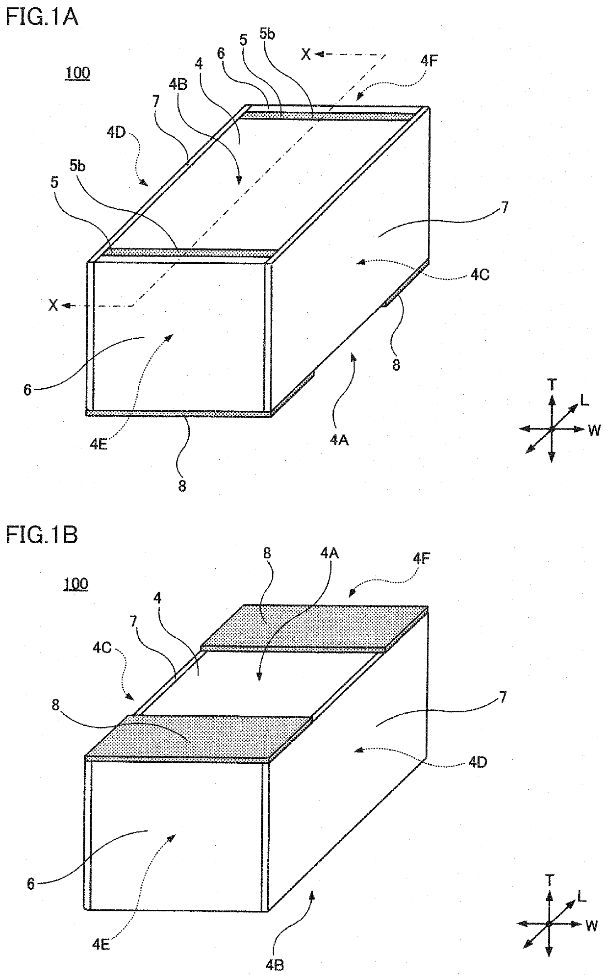
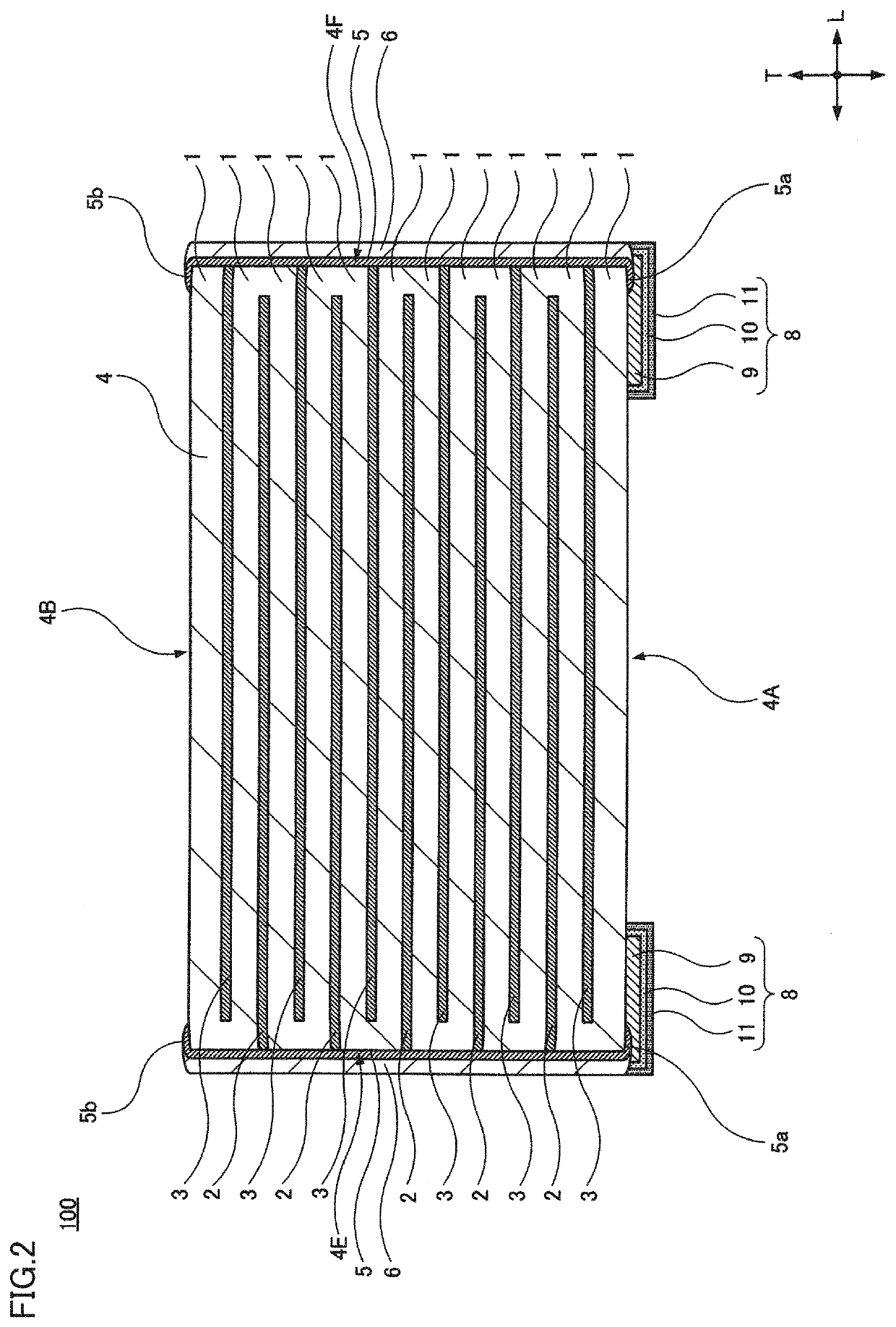
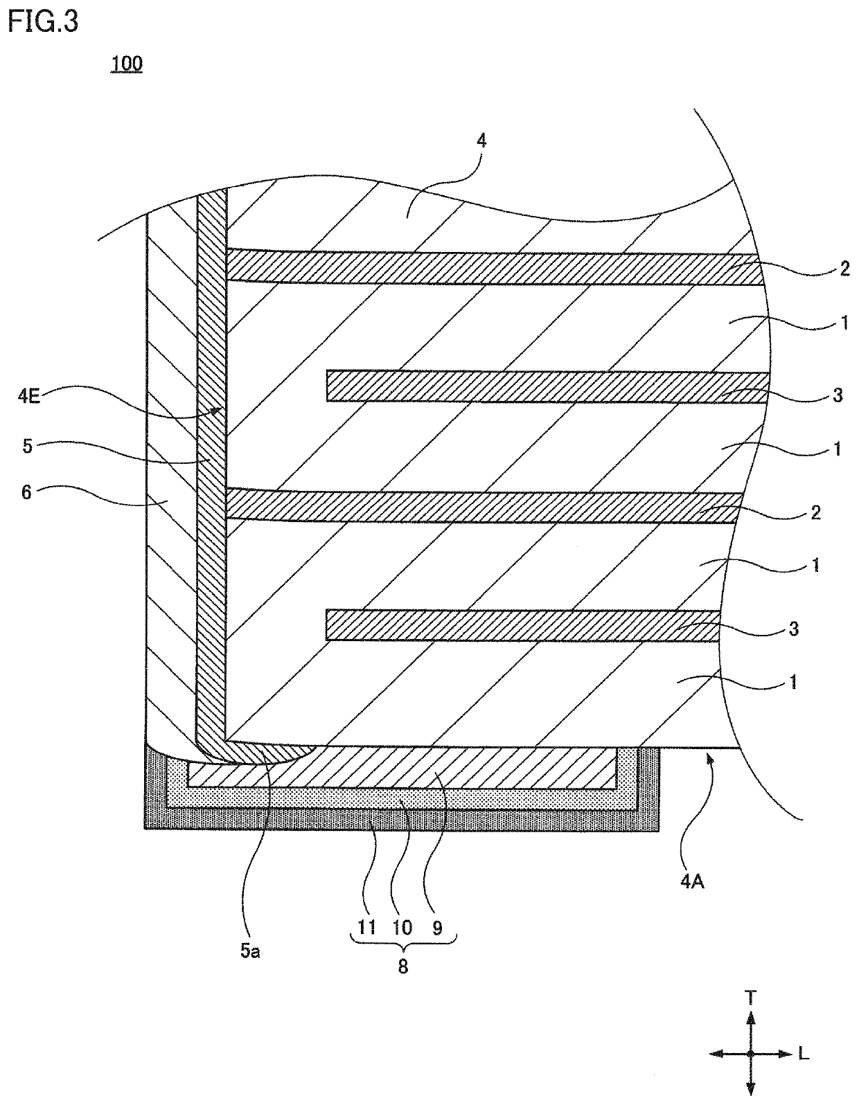
[0031]FIGS. 1A, 1B, 2, 3, and 4 show a multilayer ceramic capacitor 100 according to a first preferred embodiment. FIG. 1A is a perspective view of multilayer ceramic capacitor 100 when viewed from above (a top surface side). FIG. 1B is a perspective view of multilayer ceramic capacitor 100 when viewed from below (a mount surface side). FIG. 2 is a cross-sectional view of multilayer ceramic capacitor 100 along X-X shown with a chain dotted arrow in FIG. 1A. FIG. 3 is a cross-sectional view of a main part of multilayer ceramic capacitor 100. FIG. 4 is an exploded perspective view of multilayer ceramic capacitor 100.

[0032]The drawings may show a height direction T, a width direction W, and a length direction L of multilayer ceramic capacitor 100 and these directions may be mentioned in the description below.

[0033]Multilayer ceramic capacitor 100 includes a ceramic multilayer body 4 including a plurality of ceramic layers 1, a plurality of first internal electrodes 2, and a plurality o...

second preferred embodiment

[0079]FIGS. 9 and 10 show a multilayer ceramic capacitor 200 according to a second preferred embodiment of the present invention. FIG. 9 is a perspective view of multilayer ceramic capacitor 200 when viewed from above (the top surface side). FIG. 10 is a cross-sectional view of multilayer ceramic capacitor 200 along Y-Y shown with a chain dotted arrow in FIG. 9.

[0080]Multilayer ceramic capacitor 200 according to the second preferred embodiment is obtained by partially modifying the construction of multilayer ceramic capacitor 100 according to the first preferred embodiment. Specifically, in multilayer ceramic capacitor 100, external electrode 8 has a rectangular or substantially rectangular shape when viewed in height direction T and provided on first main surface 4A of ceramic multilayer body 4, which is modified in multilayer ceramic capacitor 200. An external electrode 28 has a cap shape on each of first end surface 4E and second end surface 4F of ceramic multilayer body 4.

[0081]...


PUM

PropertyMeasurementUnit
Lengthaaaaaaaaaa
Thicknessaaaaaaaaaa
Thicknessaaaaaaaaaa

Abstract

A multilayer ceramic capacitor includes a ceramic multilayer body including ceramic layers and internal electrodes that are layered, main surfaces, side surfaces, and end surfaces, a conductor layer covering each of the end surfaces of the ceramic multilayer body and electrically connected to the internal electrodes, an insulating layer covering the conductor layer, and an external electrode electrically connected to the conductor layer. The conductor layer includes a portion that extends to a portion of each of the main surfaces of the ceramic multilayer body.

Description

CROSS REFERENCE TO RELATED APPLICATIONS[0001]This application claims the benefit of priority to Japanese Patent Application No. 2019-131514 filed on Jul. 16, 2019. The entire contents of this application are hereby incorporated herein by reference.BACKGROUND OF THE INVENTION1. Field of the Invention[0002]The present invention relates to a multilayer ceramic capacitor and, more specifically, to a multilayer ceramic capacitor in which a conductor layer covers an end surface of a ceramic multilayer body and an insulating layer covers the conductor layer.2. Description of the Related Art[0003]Japanese Patent Laid-Open No. 2017-175037 discloses a multilayer ceramic capacitor in which a conductor layer is formed to cover an end surface of a ceramic multilayer body and an insulating layer is formed to cover the conductor layer. The multilayer ceramic capacitor disclosed in Japanese Patent Laid-Open No. 2017-175037 achieves improved moisture resistance by covering the end surface of the cer...

Claims


Application Information

Patent Timeline
IPC IPC(8): H01G4/30H01G2/06H01G4/008H01G4/012H01G4/12
CPCH01G4/30H01G2/065H01G4/12H01G4/012H01G4/008H01G4/232H01G4/0085H01G4/2325H01G4/252
Inventor KUROSU, YUTAWAKASHIMA, MASAHIRO
Owner MURATA MFG CO LTD
Why Eureka
Try Eureka