
Actuator device and actuation method

Pending Publication Date: 2021-01-21
KONINKLJIJKE PHILIPS NV
View PDF1 Cites 1 Cited by
  • Summary
  • Abstract
  • Description
  • Claims
  • Application Information

AI Technical Summary

Benefits of technology

This invention is about using AC signals to help shape a faster actuation response of an EAP actuator. The use of AC signals allows for a reduction in the overdrive signal needed to achieve the same overall deformation response. By synchronizing the actuation signal and AC signal, the fastest actuation response can be achieved, which is most likely a single step response. However, some small delay between the signals may not result in any perceible decrease in the speed or sharpness of the step response.

Problems solved by technology

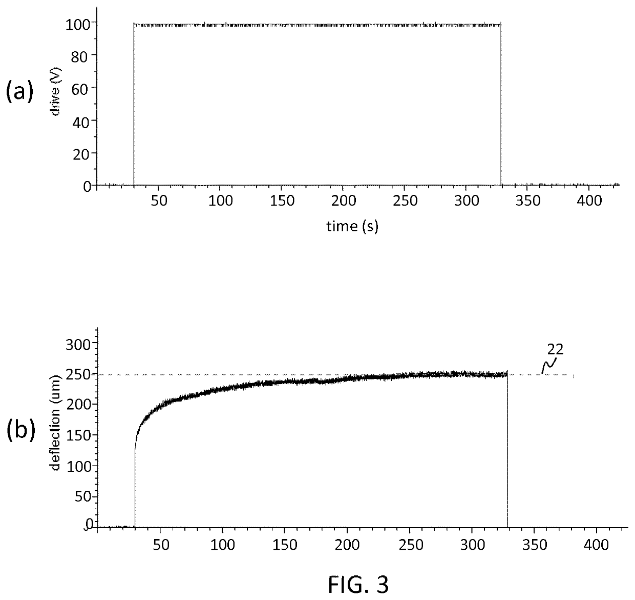
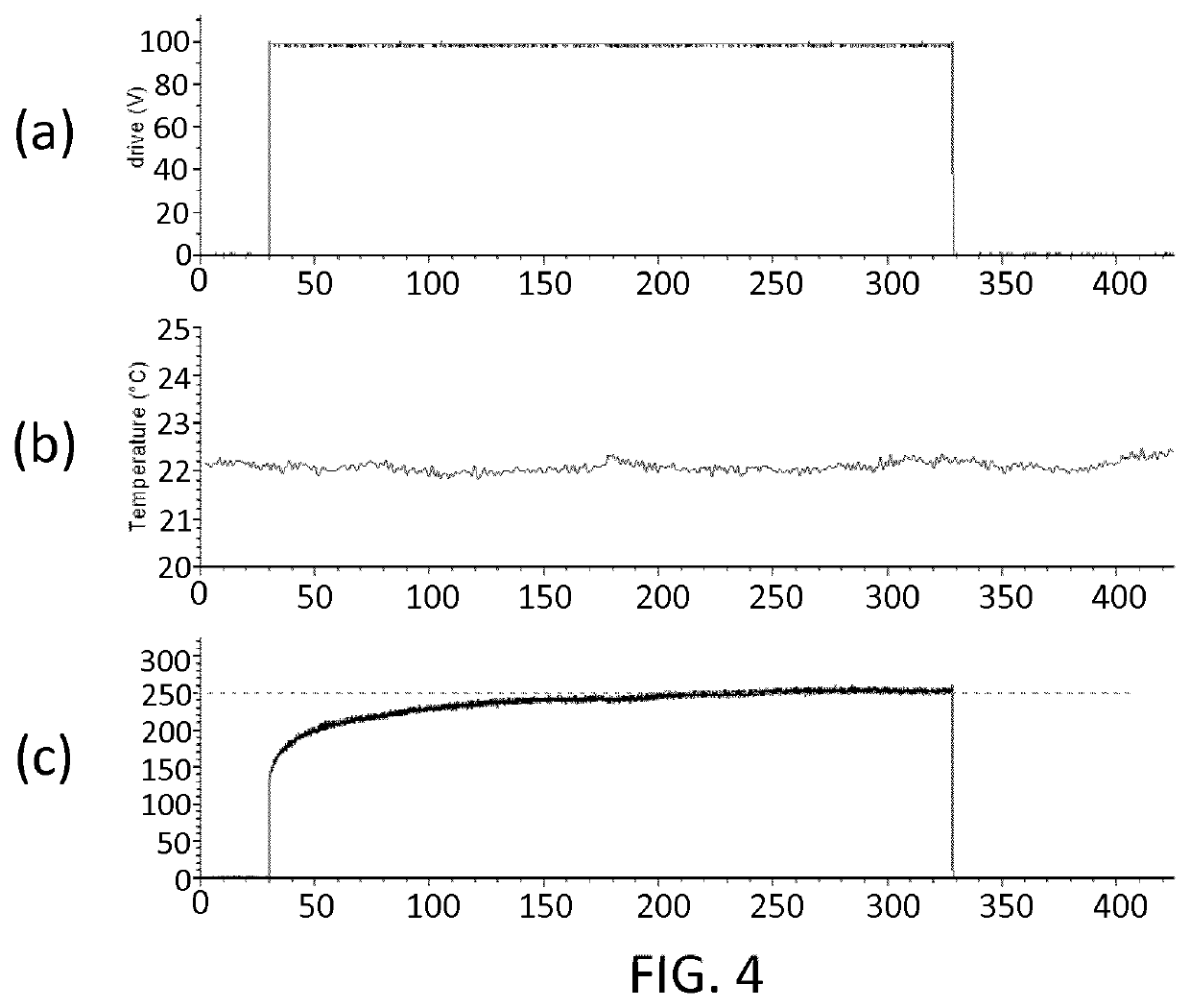
In practice however, EAP actuators respond too slowly to applied step voltages to achieve this.
This undermines rapidity of response and also positional stability of the actuator: precise positional placement of an actuator cannot be achieved on short time scales, due to the slow upward drift toward a final deformation position.
However, this solution requires reasonably high overdrive voltage amplitudes, which limits their applicability at high driving amplitudes and may in certain cases damage or destroy the responsive characteristics of the EAP material.

Method used


Image

  • Actuator device and actuation method
  • Actuator device and actuation method
  • Actuator device and actuation method

Examples


Embodiment Construction

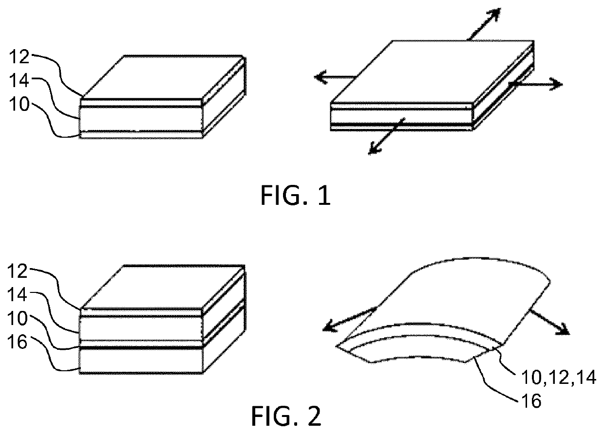
[0060]The invention will be described with reference to the Figures.

[0061]It should be understood that the detailed description and specific examples, while indicating exemplary embodiments of the apparatus, systems and methods, are intended for purposes of illustration only and are not intended to limit the scope of the invention. These and other features, aspects, and advantages of the apparatus, systems and methods of the present invention will become better understood from the following description, appended claims, and accompanying drawings. It should be understood that the Figures are merely schematic and are not drawn to scale. It should also be understood that the same reference numerals are used throughout the Figures to indicate the same or similar parts.

[0062]The actuator device as defined herein comprises an actuator member which incorporates an electroactive material, usually mad of an electroactive polymer material. A controller controls supply of an actuation signal a...


PUM


Abstract

An actuator device comprises an actuator member (62) which incorporates an electroactive polymer material. A controller (72) controls supply of an actuation signal and a superposed AC signal, which has the effect of inducing heating. The actuator member has a known set of deformation or deflection responses to applied actuation signals of different levels, and a known set of oppositely direction deformation or deflection responses to applied AC signals of different levels. To achieve accelerated actuation response, an actuation signal is supplied of higher signal level than known to be necessary to realize a given desired actuation level, and an AC signal is supplied of a level sufficient to reduce the resultant actuation response to the desired level. In examples, the overdrive part of the actuation signal and the AC signal may be tapered off after realizing the desired actuation level.

Description

FIELD OF THE INVENTION[0001]This invention relates to an actuator device and method, and in particular an electroactive polymer actuator device and method.BACKGROUND OF THE INVENTION[0002]Electroactive materials (EAMs) are a class of materials within the field of electrically responsive materials. When implemented in an actuation device, subjecting an EAM to an electrical drive signal can make it change in size and / or shape. This effect can be used for actuation and sensing purposes. There exist inorganic and organic EAMs. One particular kind of organic EAM is that of electroactive polymers (EAPs).[0003]Electroactive polymers (EAPs) are an emerging class of materials within the field of electrically responsive materials. EAPs can work as sensors or actuators and can easily be manufactured into various shapes allowing easy integration into a large variety of systems.[0004]Materials have been developed with characteristics such as actuation stress and strain which have improved signif...

Claims


Application Information

Patent Timeline
IPC IPC(8): H01L41/04H01L41/193H01L41/09
CPCH01L41/042H01L41/0926H01L41/193H10N30/802H10N30/204H10N30/857
Inventor HILGERS, ACHIM RUDOLF
Owner KONINKLJIJKE PHILIPS NV
Features
  • Generate Ideas
  • Intellectual Property
  • Life Sciences
  • Materials
  • Tech Scout
  • Unparalleled Data Quality
  • Higher Quality Content
  • 60% Fewer Hallucinations
Learn More