Steering column for a motor vehicle

a technology for steering columns and motor vehicles, applied in the direction of mechanical energy handling, dynamo-electric components, transportation and packaging, etc., can solve the problems of only being implemented with high complexity, and cannot be implemented, and achieve the effect of low complexity, low cost and high drive torqu

Active Publication Date: 2021-02-18
THYSSENKRUPP PRESTA AG +1
View PDF0 Cites 2 Cited by
  • Summary
  • Abstract
  • Description
  • Claims
  • Application Information

AI Technical Summary

Benefits of technology

[0026]Alternatively, it can be provided that the hollow shaft is mounted by way of a single bearing, preferably a four-point roller bearing, preferably in one of the end regions of the hollow shaft. A four-point bearing is a single-row radial angular-contact ball bearing, the races thereof being configured such that, apart from radial loads, axial loads can also be absorbed in both directions. It is an advantage of this embodiment that a four-point bearing in the axial direction requires significantly less space than double-row bearings.
[0027]The drive motor is preferably configured as a servomotor. A servomotor of this type in a small construction mode can deliver a sufficiently high drive torque for directly rotating the spindle nut for the adjustment of the steering column, is practically maintenance-free and reliable.
[0028]A motor-adjustable steering column for a moto

Problems solved by technology

In the prior art, this cannot be implemented, or be implemented only with high complexity, o

Method used


Image

  • Steering column for a motor vehicle
  • Steering column for a motor vehicle
  • Steering column for a motor vehicle

Examples


first embodiment

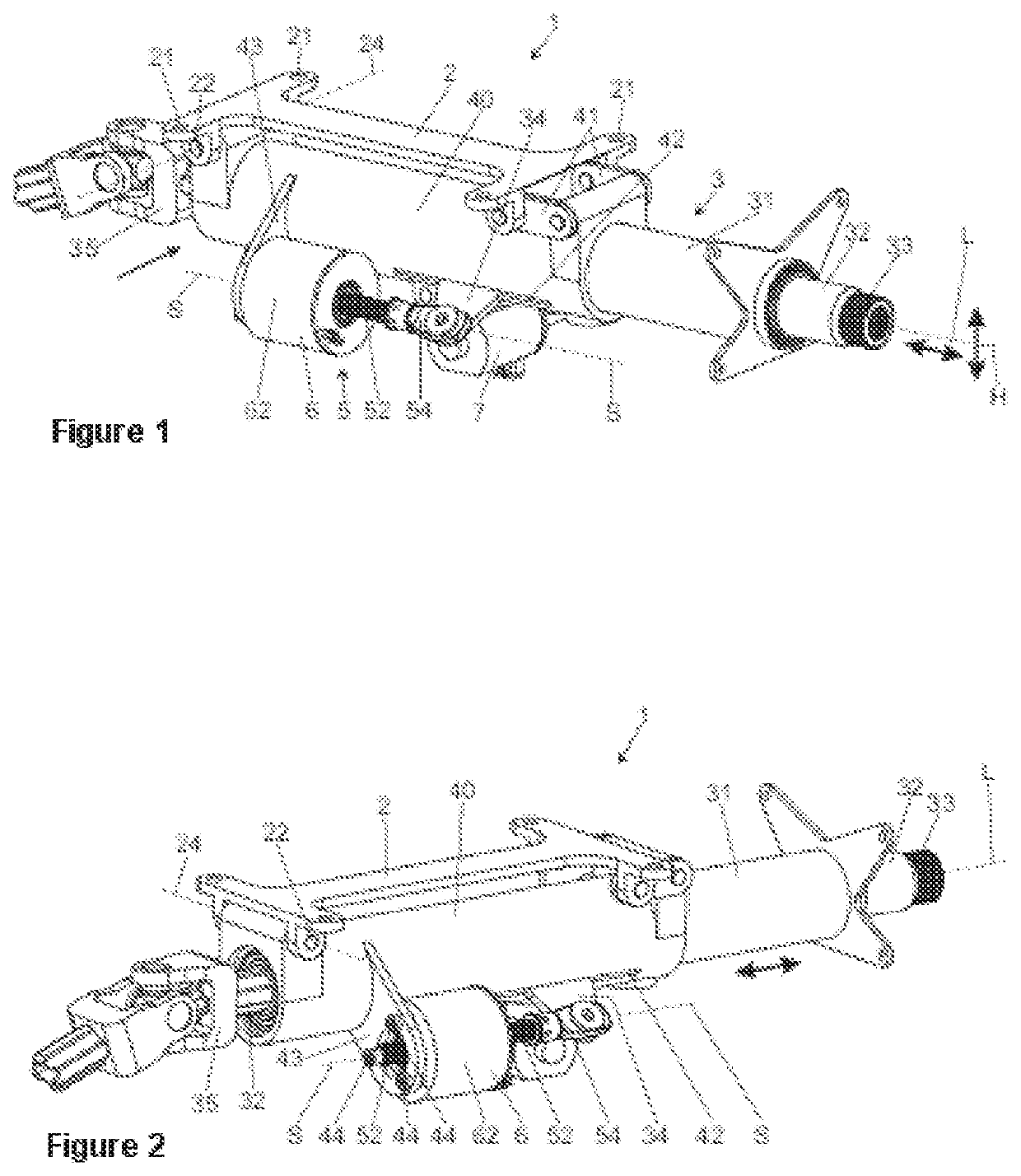
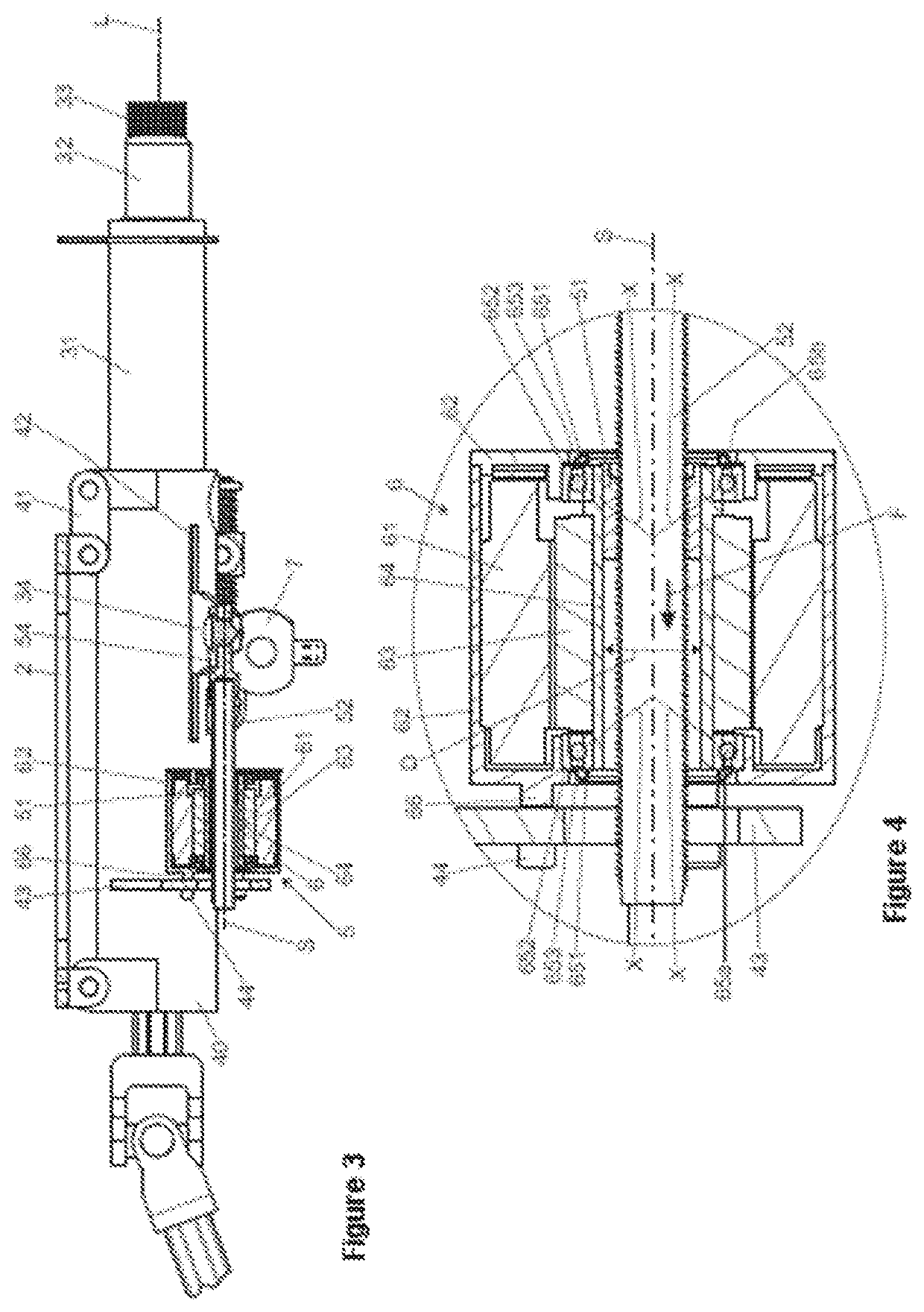
[0059]On account of the described disposal of the spindle nut 51 in the rotor shaft 64, an energy absorbing installation in a first embodiment is implemented in the embodiment shown in FIG. 4. In the event of a crash, for example in the event of a frontal collision, a high force F in the direction of the longitudinal axis L on account of a body impacting the steering wheel is introduced by way of the steering spindle 32 into the internal casing tube 31, and by way of the transmission element 34 is transmitted to the threaded spindle 52. This force F, also referred to as the crash force, in the direction of the spindle axis S is directed by way of the spindle nut 51 into the rotor shaft 64, and by way of the bearing 65a, b and the stator housing 62 on the support console 43 is finally absorbed on the external casing tube 40. Consequently, as is plotted in FIG. 4, the crash force F acts in the axial direction on the connection between the spindle nut 51 and the rotor shaft 64.

[0060]Wh...

third embodiment

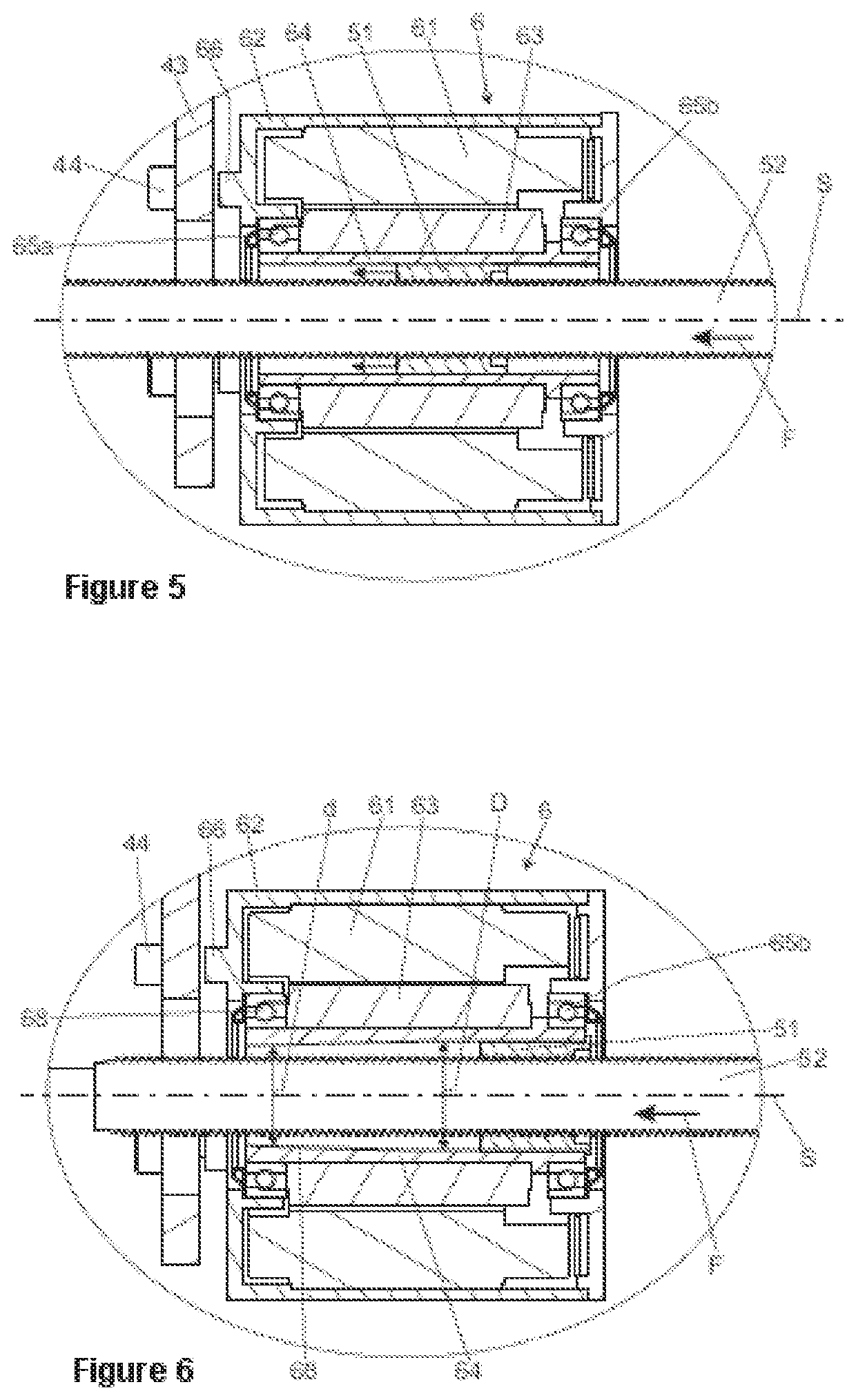
[0067]A third embodiment is illustrated in FIGS. 7 to 9, wherein the steering column 1 of FIGS. 7 to 9 has a construction which is identical to that of the steering column from FIGS. 1 to 5, wherein the difference lies in the space-saving and compact configuration of the adjustment drive 5 which can be seen in the cross-sectional view of FIG. 8, which shows a section A-A from FIG. 7, as well as in the schematic perspective view of FIG. 8, the stator housing 62 having been omitted for improved clarity in the latter. A particularity of the illustrated drive motor 6 in comparison to the drive motor 6 illustrated in FIGS. 1 to 5 is the asymmetrically shaped stator 61 which on the circumference thereof that faces the casing unit 4, or the longitudinal axis L, respectively, has a radial concavity 67 which enables a relatively large stator diameter for a high motor torque to be predefined and to nevertheless keep the spacing between the spindle axis S and the longitudinal axis L relatively...

second embodiment

[0068]A drive motor 6 in a second embodiment is separately illustrated in FIG. 10 in a cross-sectional view as in FIG. 8, and in FIG. 11 in an exploded illustration exploded in the direction of the spindle axis S, wherein the actuator unit has been omitted for improved clarity. The individual parts having identical functions herein are provided with the same reference signs.

[0069]In a refinement of the first embodiment, the drive motor 6 has two radial concavities 67 which in terms of the spindle axis S are formed so as to be opposite in the circumference of the stator housing 62. As in the first embodiment, said concavities 67 in the cross-sectional profile form recesses in the shape of segments of a circle. The concavities 67 can in each case have the same cross section, as is illustrated, and be disposed so as to be symmetrical in terms of the spindle axis S. The quiet running can be improved on account thereof. Moreover, asymmetrical arrangements as well as, additionally or alte...


PUM


Abstract

An adjustment drive for a motor-adjustable steering column for a motor vehicle, includes a spindle drive having a threaded spindle which engages in a spindle nut which, so as to be able to be driven in a rotating manner about the spindle axis relative to the threaded spindle, is coupled to the rotor shaft of a drive motor which has a rotor and a stator. In order to enable a compact design with minor complexity, the rotor shaft of the drive motor is configured as a hollow shaft which is disposed so as to be coaxial with the spindle axis and in which the threaded spindle is coaxially disposed.

Description

PRIOR ART[0001]The invention relates to an adjustment drive for a motor-adjustable steering column for a motor vehicle, comprising a spindle drive having a threaded spindle which engages in a spindle nut which, so as to be able to be driven in a rotating manner about the spindle axis relative to the threaded spindle, is coupled to the rotor shaft of a drive motor which has a rotor and stator. The invention furthermore relates to a motor-adjustable steering column for a motor vehicle, comprising an adjustment drive of this type, the spindle drive of said adjustment drive being disposed between a support unit that is able to be connected to the bodywork and a casing unit that rotatably receives a steering spindle, and / or between casing tubes of a casing unit that are mutually adjustable in a telescopic axial manner and mount the steering spindle.[0002]Steering columns for motor vehicles have a steering shaft having a steering spindle, a steering wheel for introducing steering command ...

Claims


Application Information

Patent Timeline
IPC IPC(8): B62D1/19B62D1/181
CPCB62D1/19B62D1/181B62D1/195H02K7/06
Inventor HUBER, SEBASTIANSPECHT, JEAN-PIERRE
Owner THYSSENKRUPP PRESTA AG
Why Eureka
Try Eureka