Method for Reducing the Amount of Ambient Radio Frequency Electromagnetic and Pulsating Magnetic Fields, Method for Drying Wet Walls, and Using the Device for Drying Wet Walls

a technology of electromagnetic and magnetic field, applied in the direction of drying, lighting and heating apparatus, furniture, etc., can solve the problems of wall wetness, wall electrical charge, wall filling, etc., and achieve the effect of convenient and complete reus

Active Publication Date: 2021-02-18
LEVAI SANDOR
View PDF0 Cites 5 Cited by
  • Summary
  • Abstract
  • Description
  • Claims
  • Application Information

AI Technical Summary

Benefits of technology

[0017]Our goal is to create such a device that is understandable and traceable for both professionals and lay users, the implementation and installation of which does not require professional training and architectural preparation, and can be easily and completely reused from the treated dried environment once its work is completed.
[0026]The object is achieved, according to an embodiment of the present invention, by a method for reducing the amount of ambient radio frequency electromagnetic and pulsating magnetic fields, comprising the steps of arranging at least one resonance circuit in a radio frequency electromagnetic and pulsating magnetic field present in a predetermined environment, supplying the resonance circuit with an antenna being in electromagnetic communication with it, supplying a plurality of resonance circuits with the energy of the ambient radio frequency electromagnetic and pulsating magnetic field transmitted by the antenna unit to the resonance circuit, and consuming at least a part of the radio frequency electromagnetic and pulsating magnetic field energy as a loss in the resonance circuits, thereby reducing the amount of the electromagnetic and pulsating magnetic fields.

Problems solved by technology

Such intensively charged areas create local “disturbance zones” or “hotspots” on the surface and, when they touch buildings, induce electrical charges in the walls, filling the bottom of the wall.
This creates an osmotic “pumping” effect in the wall that causes the wall to get wet over time.
Neutralizing or reversing these electric and / or magnetic fields in the immediate vicinity of the building will reduce the number and power of the hotspots full of these energies, which results in the cessation of the electromotive force and the osmotic pumping effect, as well as the cessation of the rising humidity.
The disadvantage of this solution, in addition to the fact that there is no scientific explanation or evidence for the nature of the referenced geogravomagnetic field, is basically the lack of the promised effect.
Based on our current scientific and proven knowledge, electroosmotic wall drying technologies use electrical systems that require external, typically electrical, energy to operate, so their long term operation of many months is typically accompanied with the costs of installation and operation.
Although there is a significant need for it, there is no known solution in the art for post-drying wet walls that provides efficient removal of moisture absorbed into the masonry at minimal implementation costs with substantially no additional operating costs.

Method used


Image

  • Method for Reducing the Amount of Ambient Radio Frequency Electromagnetic and Pulsating Magnetic Fields, Method for Drying Wet Walls, and Using the Device for Drying Wet Walls
  • Method for Reducing the Amount of Ambient Radio Frequency Electromagnetic and Pulsating Magnetic Fields, Method for Drying Wet Walls, and Using the Device for Drying Wet Walls
  • Method for Reducing the Amount of Ambient Radio Frequency Electromagnetic and Pulsating Magnetic Fields, Method for Drying Wet Walls, and Using the Device for Drying Wet Walls

Examples


Embodiment Construction

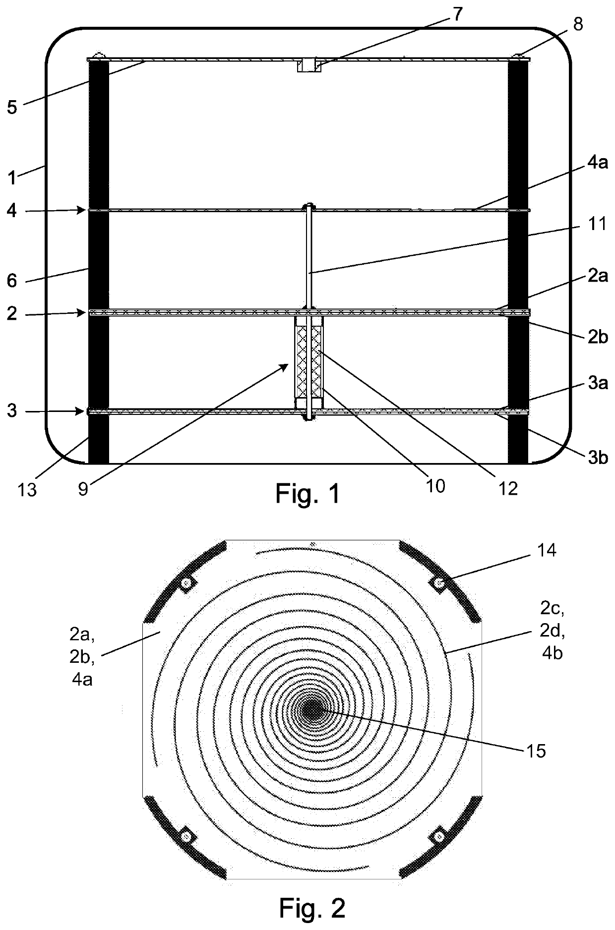
[0035]In carrying out the method, resonance circuit units 2, 3 and an antenna 4 connected to them in the device, which will be described in more detail later, are placed in a predetermined environment, for example in a building where wall wetting is experienced. With the antenna 4 the electrosmog, i.e. a radio frequency electromagnetic and pulsating magnetic field is received and the received energy is transferred to the passive resonance circuit units 2, 3 connected to the antenna 4. In present example said passive resonance circuit units 2, 3 are LC circuits. In the passive resonance circuit units 2, 3 the energy is at least partially converted by the resonance into resonance circuit loss and heat, thus reducing the amount of ambient radio frequency electromagnetic and pulsating magnetic fields to an extent that is not physically perceptible but can be experienced.

[0036]FIG. 1 shows the structure of an exemplary embodiment of the proposed device by means of a schematic vertical se...


PUM


Abstract

In a method for reducing the amount of ambient radio frequency electromagnetic and pulsating magnetic fields (“electrosmog”), resonance circuit units placed in a predetermined environment are energized by radio frequency electromagnetic and pulsating magnetic field energy transmitted to the resonance circuits by an electromagnetically connected antenna, at least a portion of energy is consumed as resonance circuit loss, reducing the amount of the ambient fields.An apparatus implementing the method comprises passive resonance circuits formed by an antenna comprising logarithmic spiral coils with identical or different pitches and passive resonance circuits formed by opposite logarithmic spiral coil panels, the resonance circuits are connected to each other and to the antenna by electrically conductive spacers, a shielding metal plate connected to ground potential is arranged adjacent to the antenna, latter is coaxial with the resonance circuit panels, which are also connected to each other via a supply line.

Description

CROSS-REFERENCE TO RELATED APPLICATION[0001]This application claims the benefit of Hungarian Patent Application No. P1900290, filed on Aug. 14, 2019, the contents of which are herein incorporated by reference in their entirety.FIELD OF THE INVENTION[0002]The present invention relates reducing ambient radio frequency electromagnetic and naturally occurring magnetic pulsations, and more particularly to methods and apparatus for drying wet walls thereby.BACKGROUND OF THE INVENTION[0003]Wetting of building foundations and masonry is a common and well-known phenomenon. Causes and possible measures of the phenomenon are well summarized in the article “Waterproofing of building foundations—wall drying by electrochemical method” published in the September 2006 issue of the Hungarian “Ezermester” magazine, the contents of which are also referred to in this description.[0004]Because our buildings are built on the ground, in direct contact with the ground, they become part of the Earth's natur...

Claims


Application Information

Patent Timeline
Patent Type & Authority Applications(United States)
IPC IPC(8): F26B3/347H05K9/00
CPCF26B3/347H05K9/00E04B1/7007H04B5/0025H04B5/0081E04B1/70H01Q1/362
Inventor LÉVAI, SÁNDOR
Owner LEVAI SANDOR
Why Eureka
Try Eureka