
Vascular occlusion devices utilizing thin film nitinol foils

a technology of nitinol foil and vascular occlusion, which is applied in the field of neurovascular aneurysm treatment methods and devices, can solve the problems of reducing the quality of life and independence, increasing direct costs for healthcare and daily living, and affecting the patient's physical and social life, so as to reduce the blood flow pattern of the aneurysm, shorten the time frame, and reduce the impact of physical strain

Active Publication Date: 2021-02-25
NANOSTRUCTURES
View PDF0 Cites 6 Cited by
  • Summary
  • Abstract
  • Description
  • Claims
  • Application Information

AI Technical Summary

Benefits of technology

The patent text discusses the need for improved solutions to treat aneurysms, which are bulging blood vessels that can cause brain damage and stroke. The current options for surgical clipping and coiling have limitations and drawbacks, such as the need for skull invention and the possibility of reestablished blood flow. The text proposes the use of NiTi thin films with meshed structures that can expand from a compressed state to a larger, expanded state when released from a catheter. The technical effects of this technology include improved access to the brain through minimally invasive procedures and better control over the risk and effects of hemorrhagic stroke.

Problems solved by technology

The economic and social costs for strokes are enormous.
While most strokes are fatal or debilitating, even mild strokes often result in impairment that greatly diminishes quality of life and independence while substantially increasing direct costs for healthcare and daily living.
Further, indirect costs such as lost productivity, expanded burden on care provided by immediate family, and the allocation of limited resources to rehabilitative therapy and convalescence aggregate to create a significant unmet need for the prevention of stroke beyond the current standard of care.
While advances in medical science, standards of care, preventative actions, and an understanding of the influences of personal lifestyle have improved in the field of stroke over time, the causes of stroke are complex and not fully understood in all instances.
If a brain aneurysm ruptures (a subarachnoid hemorrhage), it releases blood into the skull resulting in stroke.
Depending on the severity of the hemorrhage, brain damage or death may result.
In other cases, an unruptured cerebral aneurysm will cause problems by pressing on areas in the brain.
When this happens, the person may suffer from severe headaches, blurred vision, changes in speech, and neck pain, depending on what areas of the brain are affected and how severe the aneurysm is.
However, because the mechanisms of aneurysm rupture are not entirely understood, and because even aneurysms of very small size may rupture, monitoring cerebral aneurysms is an incomplete solution to meeting medical needs.
Surgical clipping remains an invasive and technically challenging procedure whereby the brain and the blood vessels are accessed through an opening in the skull.
A limitation of coiling is that eventual compression of the bolus of individual coils may occur over time and thus blood flow to the aneurysm may become reestablished.
Additionally, not all aneurysms are suitable for coiling: (1) wide-necked aneurysms require a support scaffolding (usually a stent) as a. structural support to prevent prolapse of the coil bolus into the blood vessel; (2) aneurysms that are located in the distal reaches of the neurovasculature may lie beyond the reach of current microcatheter sizing; and, (3) microcatheters filled with embolic coils are not always flexible enough to navigate the highly tortuous and fragile anatomy of neurovascular blood vessels.
Laser cut hypotubes require complex manufacturing and have limitations in the degree of expansion deformation that they can tolerate.
Alternately, braided wire forms are much less complicated to manufacture, can tolerate substantial expansion deformation, but offer very limited control of structural porosity due to the localized unconstrained movement allowable between wires that are not mechanically bound together.

Method used

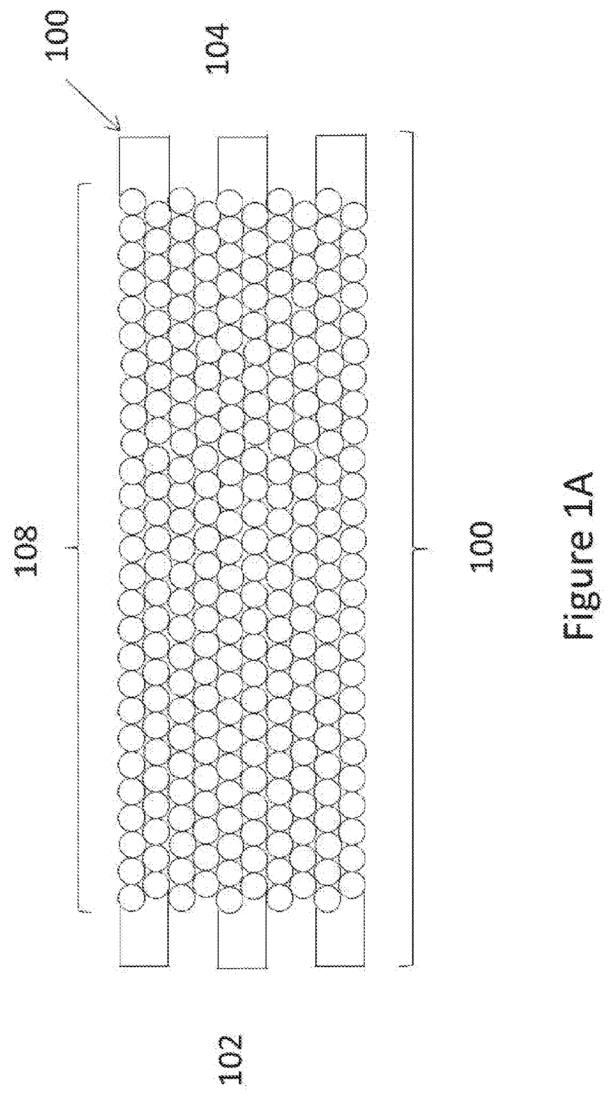
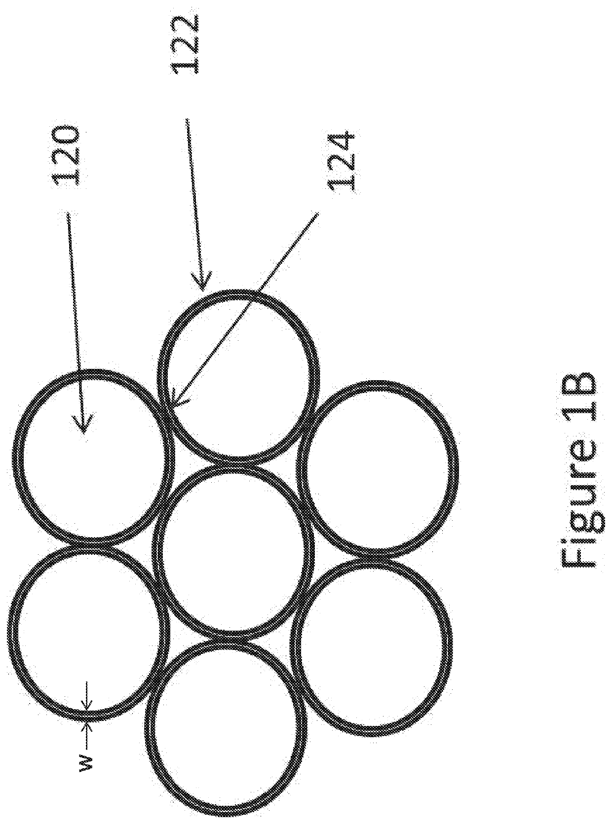
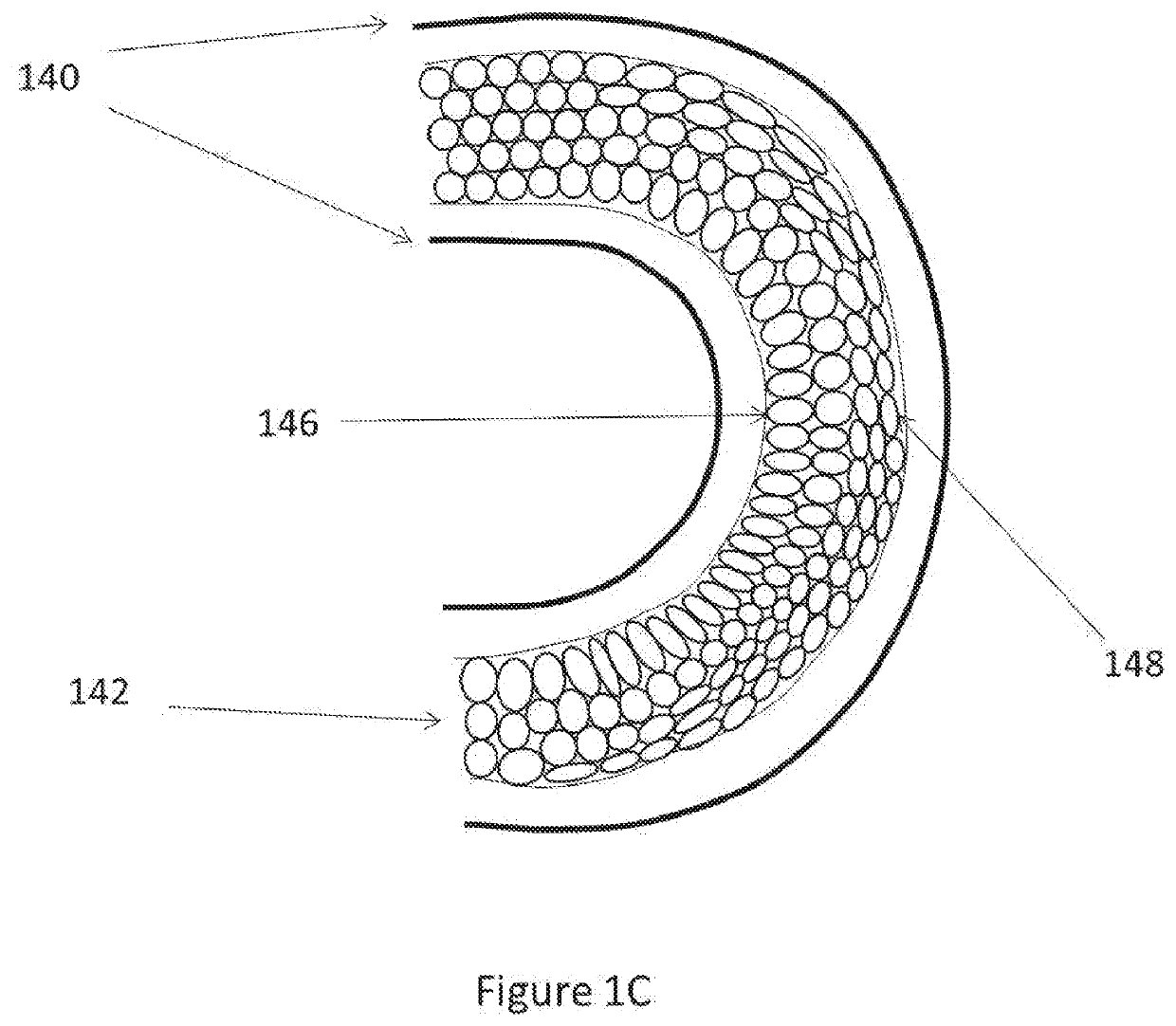

Image

  • Vascular occlusion devices utilizing thin film nitinol foils
  • Vascular occlusion devices utilizing thin film nitinol foils
  • Vascular occlusion devices utilizing thin film nitinol foils

Examples


example embodiments

[0081]The following example embodiments identify some possible permutations of combinations of features disclosed herein, although other permutations of combinations of features are also possible.

[0082]1. A deployable occlusion device for filling an aneurysm, the occlusion device comprising:[0083]a support structure comprising a wire; and[0084]a mesh component comprising a porosity, the mesh component comprising a first end portion and a second end portion, the first end portion being attached to the support structure and the second end portion being a free end, the mesh component extending radially outward from the support structure.

[0085]2. The occlusion device of Embodiment 1, wherein the mesh component is configured to transition between a compressed state and an uncompressed state, the mesh component forming a coil in the uncompressed state.

[0086]3. The occlusion device of Embodiment 2, wherein in the compressed state, the mesh componentis wrapped around the support structure.

[...


PUM


Abstract

A deployable occlusion device for filling an aneurysm. The occlusion device includes a support structure, for example a wire or otherwise elongate structure. The occlusion device also includes a mesh component having a porosity. The mesh component has a first end portion and a second end portion. The first end portion of the mesh component is attached to the support structure and the second end portion of the mesh component is a free end. The mesh component extends from the support structure.

Description

BACKGROUNDField[0001]This application is related to the methods and devices for treating neurovascular aneurysms.Description of the Related Art[0002]The worldwide occurrence of stroke is estimated to be in the vicinity of 60,000,00 instances per year. The economic and social costs for strokes are enormous. While most strokes are fatal or debilitating, even mild strokes often result in impairment that greatly diminishes quality of life and independence while substantially increasing direct costs for healthcare and daily living. Further, indirect costs such as lost productivity, expanded burden on care provided by immediate family, and the allocation of limited resources to rehabilitative therapy and convalescence aggregate to create a significant unmet need for the prevention of stroke beyond the current standard of care.[0003]While advances in medical science, standards of care, preventative actions, and an understanding of the influences of personal lifestyle have improved in the f...

Claims


Application Information

Patent Timeline
Patent Type & Authority Applications(United States)
IPC IPC(8): A61B17/12
CPCA61B17/12113A61B17/12031A61B17/12172A61B17/1215A61L31/146A61L31/18A61L31/022A61B17/12177
Inventor MAUGER, PHILIP
Owner NANOSTRUCTURES
Learn More