Hybrid Working Machine

Active Publication Date: 2021-03-04
HITACHI CONSTR MASCH CO LTD
View PDF0 Cites 4 Cited by
  • Summary
  • Abstract
  • Description
  • Claims
  • Application Information

AI Technical Summary

Benefits of technology

[0012]According to the present invention, the risk of the leakage of the heat-transfer medium (cooling medium and heat medium) can be made low

Problems solved by technology

Therefore, for example, in a case where the cooling water is leaked in the electricity storage device, there is a possibility that not only the engine cooling water to be supplied to the electricity storage device runs out but also the engine or other equipment devices using the engine cooling

Method used


Image

  • Hybrid Working Machine
  • Hybrid Working Machine
  • Hybrid Working Machine

Examples


Example

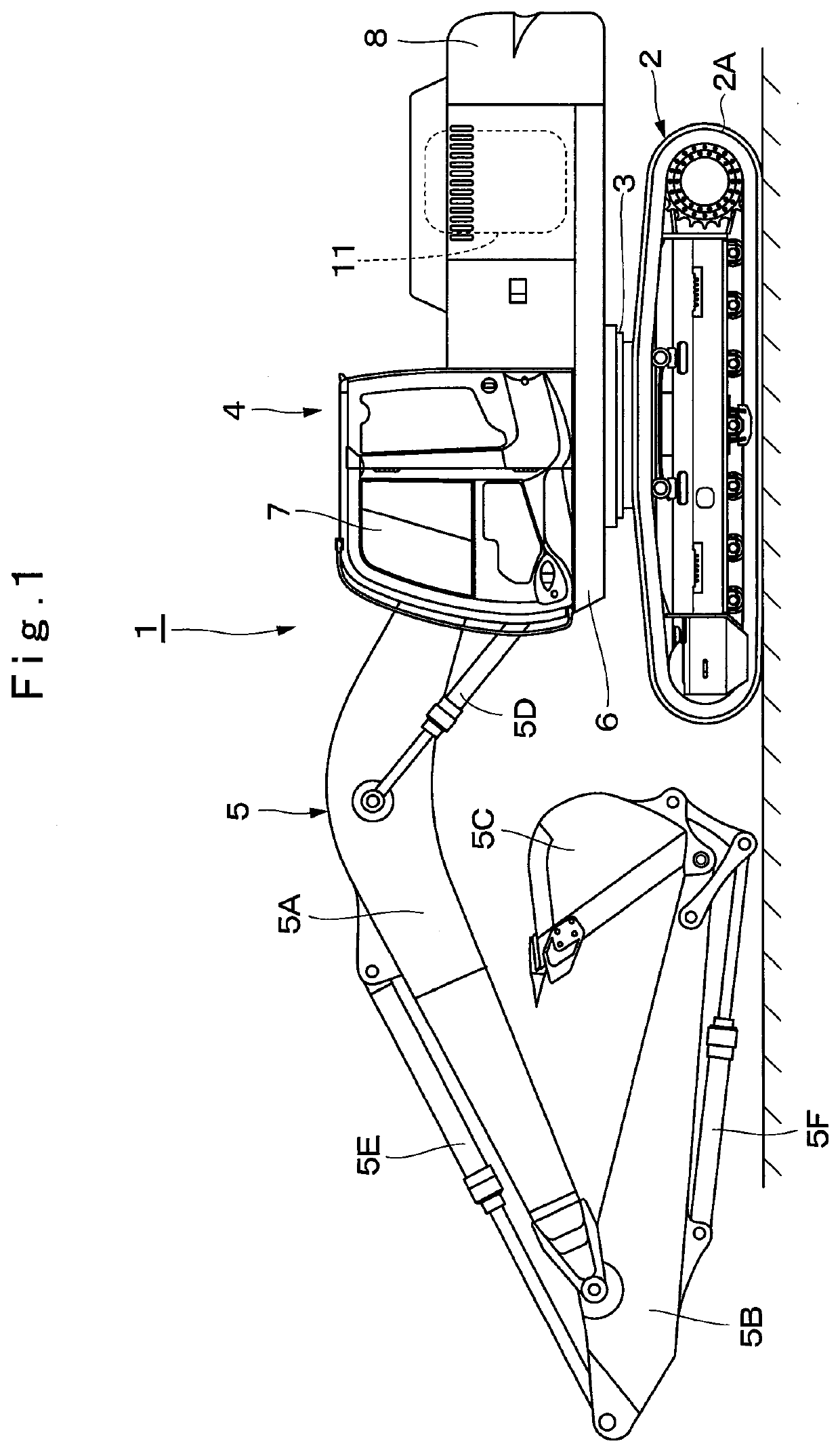
[0020]Hereinafter, an explanation will be in detail made of an embodiment of a hybrid working machine according to the present invention with reference to the accompanying drawings by taking a case of being applied to a hybrid hydraulic excavator as an example. It should be noted that each step in a flowchart shown in FIG. 7 uses notation of “S” (for example, step 1=“S1”).

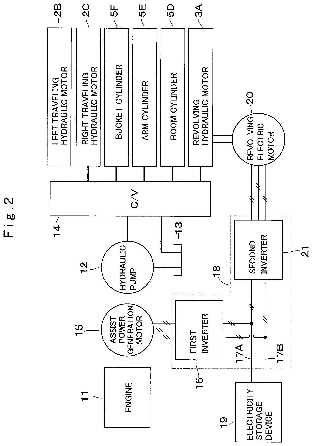
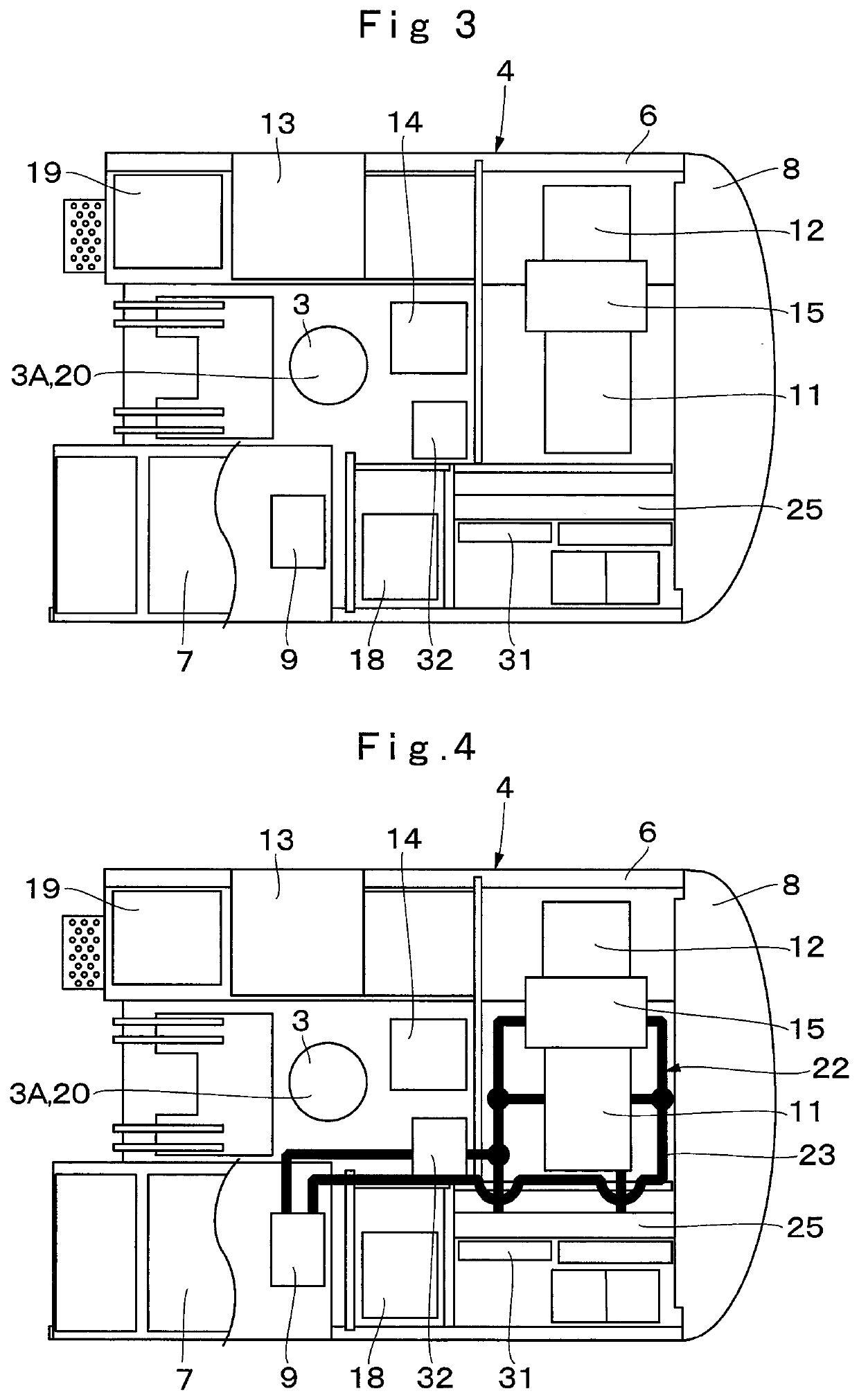
[0021]In FIG. 1, a hybrid hydraulic excavator 1 (hereinafter, referred to as “hydraulic excavator 1”) as a representative example of a hybrid working machine is provided with an engine 11 and an assist power generation motor 15 (refer to FIG. 2 to FIG. 6) as an electric motor, and an electricity storage device 19 (refer to FIG. 2 to FIG. 6), which will be described later. That is, the hydraulic excavator 1 includes an automotive lower traveling structure 2 of a crawler type, a revolving device 3 that is provided on the lower traveling structure 2, an upper revolving structure 4 that is mounted through the revolving...


PUM


Abstract

An engine cooling system (22) includes an engine (11), an engine cooling pipe line (23), an engine water pump (24) and an engine radiator (25). An electricity storage device cooling system (27) includes an electricity storage device (19), an electricity storage device cooling pipe line (28), an electricity storage device water pump (29) and an electricity storage device radiator (31). Different heat-transfer media (engine cooling water and electricity storage device cooling water) flow respectively in the engine cooling system (22) and the electricity storage device cooling system (27). Further, a heating heat exchanger (32) is provided in the halfway of the engine cooling pipe line (23) and in the halfway of the electricity storage device cooling pipe line (28) for performing heat exchange between the engine cooling water and the electricity storage device cooling water.

Description

TECHNICAL FIELD[0001]The present invention relates to hybrid working machines such as hydraulic excavators, hydraulic cranes or wheel loaders on each of which, for example, an engine, an electric motor and an electricity storage device are mounted.BACKGROUND ART[0002]For example, a hybrid working machine such a hybrid excavator operates using power stored in an electricity storage device as a power source. In such a hybrid working machine, a storage battery such as a lithium-ion battery, which configures the electricity storage device, generates heat with charge and discharge cycles, and therefore, the hybrid working machine is provided with a cooling device for cooling the storage battery. That is, in a case where a use upper limit temperature of the storage battery is 50° C., for example, the storage battery is used while being cooled with the cooling device in order to prevent a temperature of the storage battery from going beyond the use upper limit temperature. However, in a ca...

Claims


Application Information

Patent Timeline
IPC IPC(8): E02F9/08E02F9/20
CPCE02F9/0866E02F9/2075E02F9/2091E02F9/226B60H1/00278B60K2001/003H01M10/613H01M10/625H01M10/663H01M10/6568H01M2220/20B60K6/44B60W2300/17B60K11/02B60K1/00B60K2001/005B60K2001/006Y02E60/10Y02T10/62B60Y2200/92B60Y2200/41
Inventor WATANABE, AKIRATAKEUCHI, KENOSAKA, TADASHI
Owner HITACHI CONSTR MASCH CO LTD
Why Eureka
Try Eureka