Offset-cancelling capacitive MEMS gyroscope

Active Publication Date: 2021-03-04
MURATA MFG CO LTD
View PDF0 Cites 0 Cited by
  • Summary
  • Abstract
  • Description
  • Claims
  • Application Information

AI Technical Summary

Benefits of technology

The invention is a MEMS gyroscope that includes a mechanical resonator and a drive circuitry to modulate the motion of the resonator in a first direction. The sense circuitry includes a closed force feedback loop to adjust the frequency response of the resonator in a second direction. The invention has a faster settling time in the second direction than in the first direction. The offset compensation circuitry is designed to determine the effect of the drive signal on the rate signal and to counteract it. The invention is characterized by a high degree of accuracy and stability.

Problems solved by technology

At these resonant frequencies the displacement is much larger than at other frequencies at same excitation magnitude and, in the miniaturized dimensions of MEMS structures, cause non-linearity and / or over range condition that disturbs the detection.
Another challenge in gyroscope design is in minimising the offset in the output signal caused by the drive signal, which is used to drive the motion of the drive / primary element.
Other sources of error in the output offset, such as quadrature error and its compensation mechanism, are often dominating in the offset error.
However, when these other sources of error are effectively compensated, the offset error due to drive signal becomes much more pronounced in comparison.
Similarly, in inertial navigation, where the rotation of the Earth needs to be measured at higher precision than a mdps (10−3° / s), offset / drift mechanisms are problematic since they cannot be predicted and therefore mdps-accuracy is not attainable.

Method used


Image

  • Offset-cancelling capacitive MEMS gyroscope
  • Offset-cancelling capacitive MEMS gyroscope
  • Offset-cancelling capacitive MEMS gyroscope

Examples


first embodiment

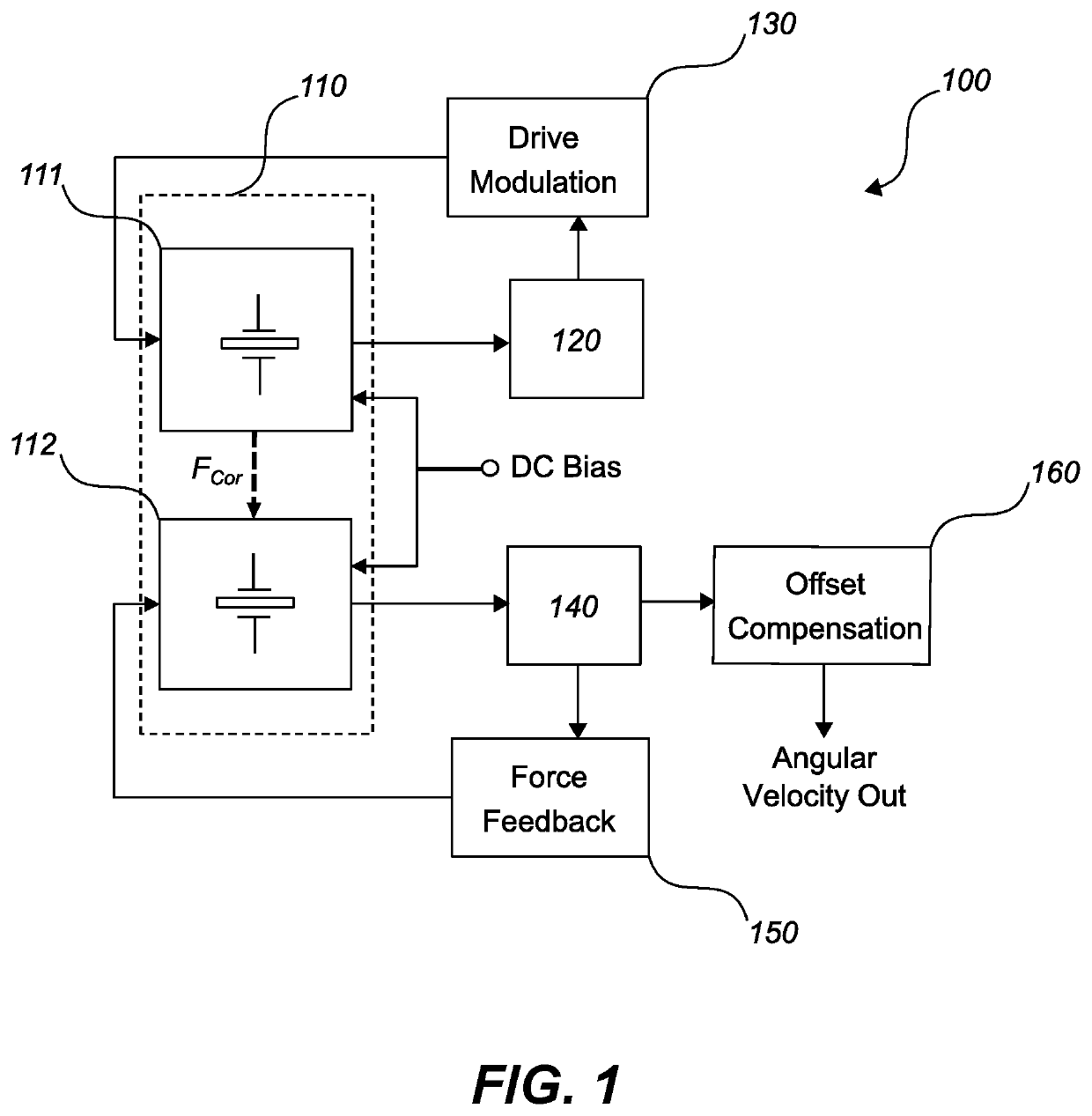
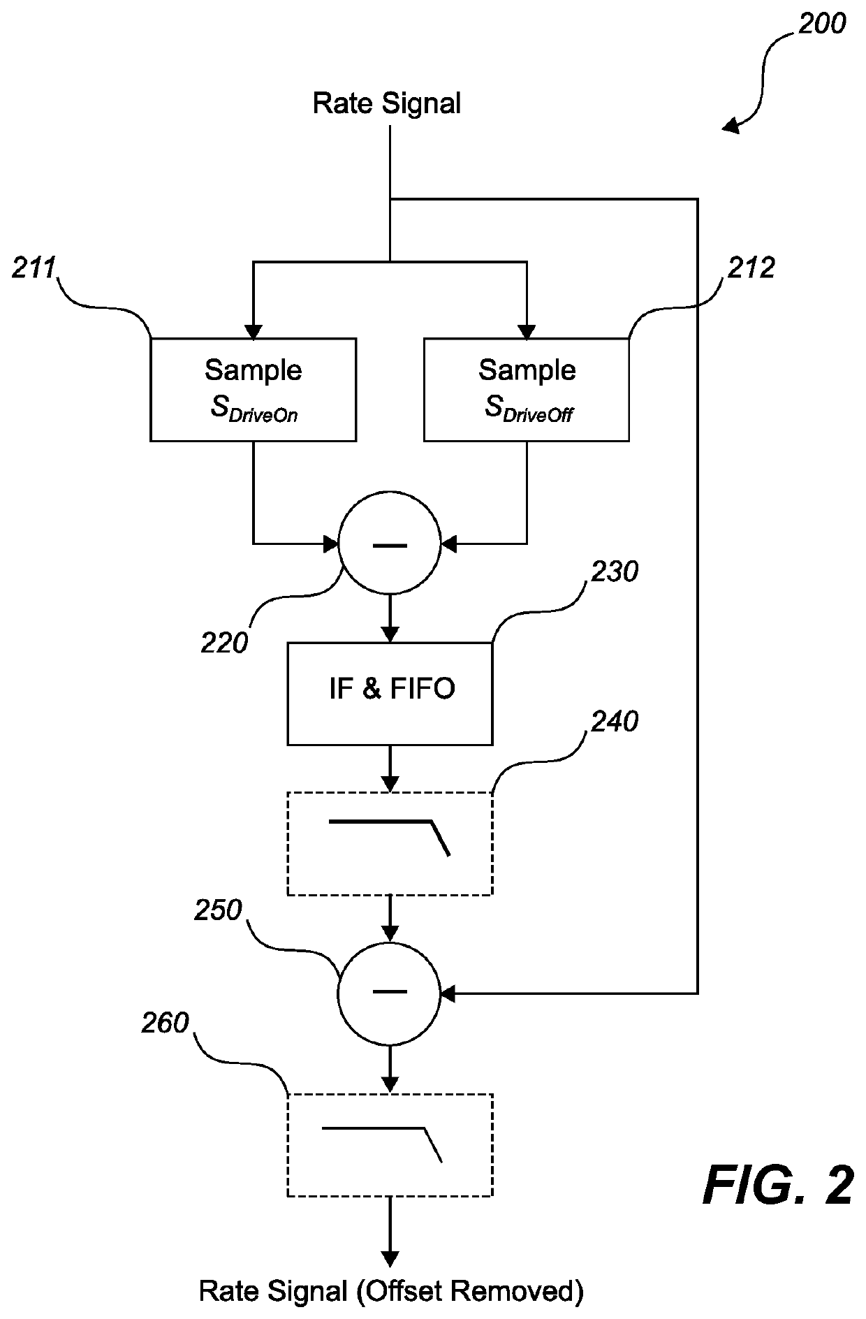
[0070]FIG. 2 depicts the function of offset cancelling circuitry 160 / 200 according to the first embodiment of the present invention. As mentioned above, in the first embodiment the drive signal is modulated such that the drive force is turned on and off repeatedly, i.e. the drive force is zeroed and fully enabled repeatedly. This type of modulation scheme typically has the drawback that the maximum rate of on / off switching is limited by the ringing time of the secondary resonator. Thus, in a conventional MEMS gyroscope without force feedback (or any MEMS gyroscope with a slower settling time) the rate of on / off switching would be severely limited to the extent that it would not be practical to use. However, in the present case, where the secondary resonator has a much faster settling time than the primary resonator, the rate of on / off switching can be greatly increased.

[0071]The offset cancelling circuitry 200 includes sampling elements 211 and 212 configured to sample the rate sign...

second embodiment

[0088]FIG. 6 depicts the function of offset cancelling circuitry 160 / 600 according to the second embodiment of the present invention. As mentioned above, in the second embodiment the drive signal is modulated linearly, such that the drive force varies continuously. In a gyroscope where the secondary element has a significantly lower Q value than the primary elements, such as a gyroscope including force feedback functionality, the modulation of the drive signal in this way has very little effect on the motion of the primary element 111, but has a clear effect on the rate signal. Indeed, using the modulation scheme depicted in FIG. 6 (with an exemplary modulation depth of 50%), the primary resonator 111 with a moderate Q value of 5000 has only 0.08% peak-to-peak variation.

[0089]The drive signal has two components: a DC component and an AC component. By recovering the AC component of the rate signal offset and comparing it to the AC component of the drive signal, the magnitude of the D...


PUM


Abstract

The present invention relates to a capacitive MEMS gyroscope with drive-signal induced offset cancelling features. In a MEMS gyroscope of the type including force feedback circuitry, the drive signal is modulated according to a known modulation scheme or frequency. The modulation scheme / frequency of the drive signal is used by offset cancelling circuitry to determine the offset in the rate signal caused by the drive signal. The determined offset is subsequently removed from the rate signal.

Description

TECHNICAL FIELD[0001]The present invention relates to micro-electro-mechanical (MEMS) gyroscopes and especially to a MEMS gyroscope configured to cancel the offset in the gyroscope output caused by the effect of the gyroscope's drive signal.BACKGROUND[0002]Motion can be considered to have six degrees of freedom: translations in three orthogonal directions and rotations around three orthogonal axes. The latter three may be measured by an angular rate sensor, also known as a gyroscope. MEMS gyroscopes use the Coriolis effect to measure the angular rate. When a mass is driven in one direction and rotational angular velocity is applied about axis orthogonal to the driven axis, the mass experiences a force in the orthogonal direction with respect to both driven and rotated axes as a result of the Coriolis force. The resulting physical displacement caused by the Coriolis force may then be read from, for example, a capacitive, piezoelectrical or piezoresistive sensing structure.[0003]In ME...

Claims


Application Information

Patent Timeline
IPC IPC(8): G01C19/5712B81B3/00
CPCG01C19/5712B81B2201/0242B81B3/0018G01C19/5726G01C19/5776
Inventor AALTONEN, LASSEBLOMQVIST, ANSSI
Owner MURATA MFG CO LTD
Why Eureka
Try Eureka