Protective device

a technology of protective devices and sensors, applied in the direction of measurement devices, fluid pressure measurement, instruments, etc., can solve the problems of thermal shock on the sensor signal of a sensor placed within a pressure chamber, affecting the detected sensor signal or damage to the sensor element, and cannot be eliminated

Active Publication Date: 2021-03-04
KISTLER HLDG AG
View PDF11 Cites 1 Cited by
  • Summary
  • Abstract
  • Description
  • Claims
  • Application Information

AI Technical Summary

Benefits of technology

[0024]The configuration of the protective device is such that the ratio of the sum of the clear widths of the passages on the membrane side or the medium side to the surface of the membrane is at least 0.25. This increases the resonance frequency and the cutoff frequency and rapid pressure changes such as those occurring in an internal combustion engine are detected eliminating any effect of the resonance frequency.

Problems solved by technology

However, the sensor element of a pressure sensor exhibits temperature dependence representing an undesired effect on the sensor signal.
This increase in membrane temperature is at least partially transferred upon the sensor element and thereby affects the detected sensor signal or damages the sensor element.
This effect on the sensor signal leads to detection of incorrect values for the physical parameter, however, in the following said detected physical parameter is not the temperature itself.
In contrast to an almost constant ambient temperature that exhibits a slow variation over time, the impact of a thermal shock on the sensor signal of a sensor placed within a pressure chamber cannot be eliminated altogether or only insufficiently can it be minimized in the context of a calibration.
Furthermore, if the temperature exceeds a material-dependent threshold value for the material of the membrane, then the membrane will be damaged by the thermal shock.
Moreover, repeated thermal shocks cause ageing of the membrane resulting in age-related damage to the membrane.
This flame protection design has the disadvantage that electromagnetic radiation generated by at least one source of radiation on the side of the medium may directly act upon the membrane through the passages and accordingly may lead to thermal shock.
This thermal shock affects the sensor signal in a way that causes incorrect values for the physical parameter to be detected by the sensor.
Depending on the intensity of the electromagnetic radiation, the electromagnetic radiation may damage the membrane and / or the sensor element.

Method used


Image

  • Protective device
  • Protective device
  • Protective device

Examples


Embodiment Construction

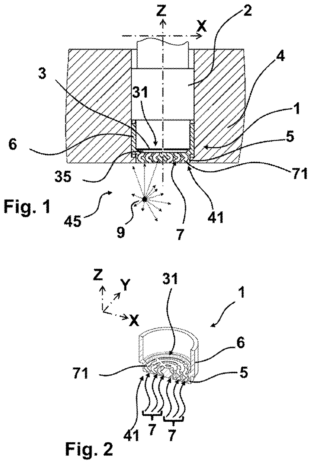
[0032]FIG. 1 shows a sectional view of the protective device 1 in a preferred embodiment that comprises a sensor 2 in an installation part 4 such as a section of a wall of a pressure chamber. Sensor 2 is not represented with section hatching for purposes of clarity.

[0033]The sensor 2 is substantially rod-shaped along the longitudinal axis Z, from which the two radially extending axes X and Y originate as schematically shown in FIG. 2. Sensor 2 is shown incorporated in an installation part 4 in FIG. 1. Advantageously, sensor 2 is introduced in the installation part 4. Installation part 4 delimits a chamber volume 45 in which the physical parameter is to be detected. The medium being the carrier of the physical parameter is in the chamber volume 45. Sensor 2 comprises the membrane 3 which extends parallel to a first radial axis X and parallel to a second radial axis Y at that end of the sensor 2 that faces the chamber volume 45. The longitudinal axis Z, first radial axis X and second ...


PUM

PropertyMeasurementUnit
roughnessaaaaaaaaaa
temperaturesaaaaaaaaaa
center anglesaaaaaaaaaa

Abstract

A protective device for a membrane of a sensor that detects a physical parameter acting upon the membrane includes a hollow main body that elongates in a direction along a longitudinal axis. The main body is open at one opposite end of the main body along the longitudinal axis, and at the end of the main body opposite the open end the protective device includes a bottom in which is defined a passage through which the medium is able reach the membrane when the protective device is attached to the sensor. The passage is defined in part by a wall that is configured so that the electromagnetic radiation propagating in the passage cannot reach the membrane without being reflected at least once on the wall.

Description

CROSS REFERENCE TO RELATED APPLICATIONS[0001]This application is a continuation of copending International Application No. PCT / EP2018 / 085885, filed Dec. 19, 2018, which is hereby incorporated herein by this reference in its entirety for all purposes.FIELD OF THE INVENTION[0002]The invention relates to a protective device to be attached to a sensor and particularly to protect the sensor's membrane that detects a physical parameter transmitted through a medium acting on the membrane.BACKGROUND OF THE INVENTION[0003]A sensor detects a physical parameter and provides a sensor signal equivalent to the physical parameter under ideal conditions. For this purpose, a sensor element having a sensitivity for the physical parameter is arranged in a sensor. Usually, the sensor element is protected against certain external impacts such as for example dust and / or liquids and / or gases and / or electromagnetic radiation by a protective layer of the sensor such as a membrane. The term and / or is to be u...

Claims


Application Information

Patent Timeline
Patent Type & Authority Applications(United States)
IPC IPC(8): G01L19/06
CPCG01L19/069
Inventor HEER, CHRISTIAN
Owner KISTLER HLDG AG
Why Eureka
Try Eureka