

Conveyance simulation device and conveyance system
- Summary
- Abstract
- Description
- Claims
- Application Information
AI Technical Summary
Benefits of technology
Problems solved by technology
Method used
Image

Examples
first embodiment
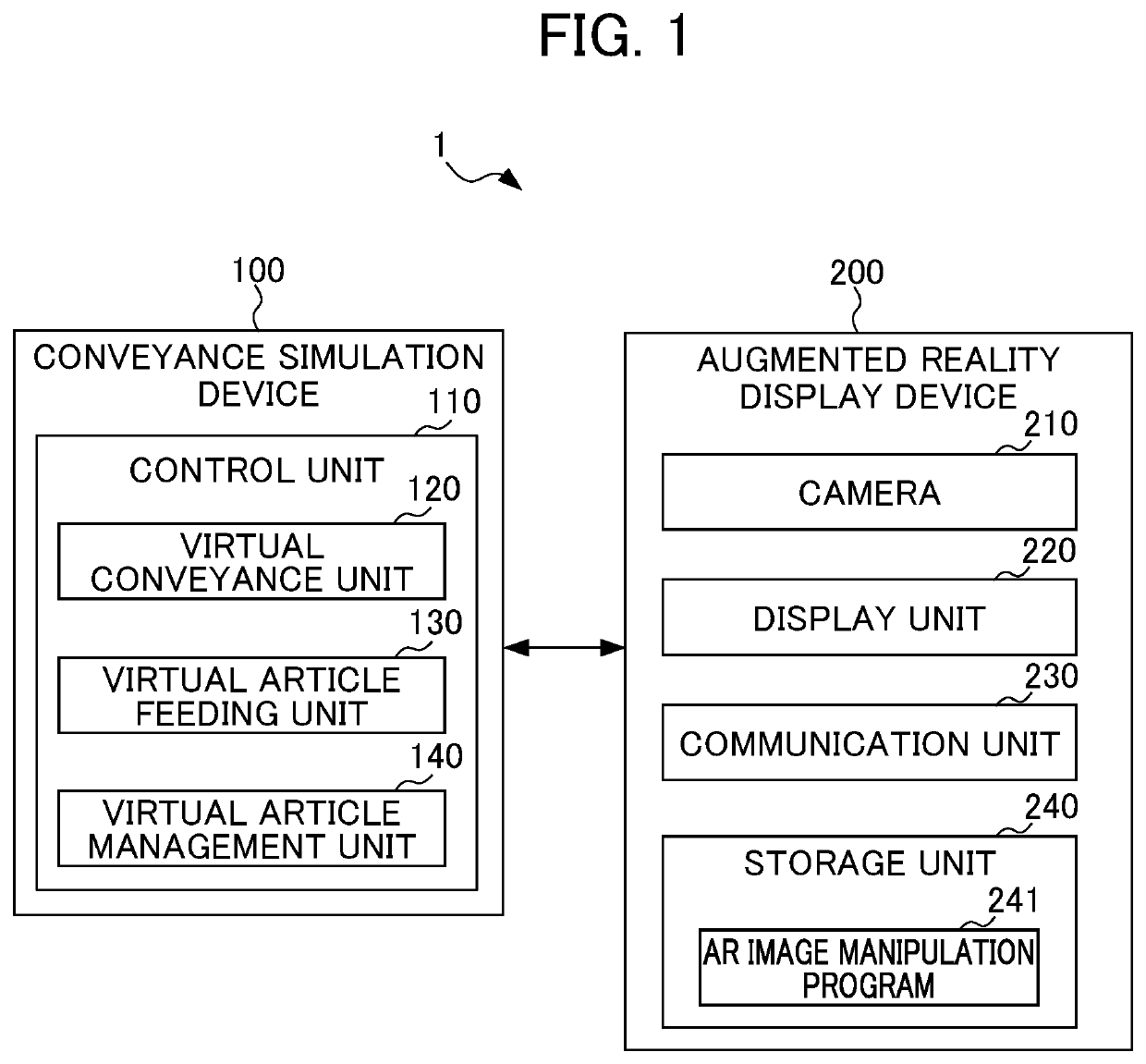
[0021]First, the present embodiment will be schematically described. According to the present embodiment, a conveyance simulation device includes: a virtual conveyance unit that is arranged in a virtual space based on a plan of a design stage of an actual worksite; a virtual article feeding unit that feeds virtual articles to the virtual conveyance unit under a predetermined condition; and a virtual article management unit that sequentially updates the positions of the virtual articles in accordance with movement of the virtual conveyance unit, whereby a flow of articles is simulated.
[0022]Thus, the present embodiment enables achievement of the object, i.e., “accurately simulating a flow of articles in an environment similar to an actual worksite”.
[0023]The foregoing summarizes the present embodiment.
[0024]Next, the configuration of the present embodiment will be described in detail with reference to the drawings.
[0025]FIG. 1 is a block diagram showing an overall configuration of a ...
second embodiment
[0094]A conveyance system 2 according to a second embodiment differs from the first embodiment in that a conveyance unit is installed at an actual worksite, a virtual article feeding unit 130a feeds virtual articles to the conveyance unit under a predetermined condition, and a virtual article management unit 140a sequentially updates positions of the virtual articles in accordance with an amount of movement of the conveyance unit, thereby simulating a flow of articles.
[0095]Thus, the conveyance system 2 can simulate the flow of articles accurately in an environment similar to the actual worksite.
[0096]The second embodiment will be described below.
[0097]FIG. 6 is a block diagram showing an overall configuration of the conveyance system according to the second embodiment. Note that elements that are the same or similar in function to those shown in FIG. 1 are denoted by the same reference characters, and a detailed description thereof will be omitted.
[0098]As shown in FIG. 6, the conv...
modification 1
[0148]In the first embodiment described above, the conveyance simulation device 100 is constituted by a single computer. However, the present disclosure is not limited thereto. For example, the conveyance simulation device 100 may be included in the control device 400.
[0149]Further, a server or the like may include part or all of the virtual conveyance unit 120, the virtual article feeding unit 130, and the virtual article management unit 140 of the conveyance simulation device 100. The functions of the conveyance simulation device 100 may be implemented using a virtual server function or the like on a cloud.
[0150]Furthermore, the conveyance simulation device 100 may be configured as a distributed processing system in which the functions of the conveyance simulation device 100 are appropriately distributed to a plurality of servers.
[0151]Likewise, a server or the like may include part or all of the virtual article feeding unit 130a and the virtual article management unit 140a of con...
PUM
 Abstract
Description
Claims
Application Information