Pneumatic tire

a technology of pneumatic tires and pneumatic components, applied in the field of pneumatic tires, can solve the problems of increasing the deformation amount of tires accordingly, unable to obtain sufficient reading performance, etc., and achieve the effect of maintaining sufficient reading performance and suppressing damage and deformation of electronic components

Active Publication Date: 2021-03-11
SUMITOMO RUBBER IND LTD
View PDF0 Cites 0 Cited by
  • Summary
  • Abstract
  • Description
  • Claims
  • Application Information

AI Technical Summary

Benefits of technology

[0029]According to the present invention, a manufacturing technology for a tire is provided which can manufacture a tire capable of suppressing damage and deformation of the electronic component and maintaining sufficient reading performance, even in the case of traveling a tire having an electronic component provided therein under high speed and severe handling.

Problems solved by technology

As a result of steadies for solving the above-mentioned problems, the present inventors have thought that increase in internal temperature of tire is the cause of why the electronic component is damaged and deformed and sufficient reading performance cannot be obtained, when traveling is performed under high speed and severe handling.
That is, th.e internal temperature of tire is 50 to 70° C. in normal traveling, but, when performing traveling under high-speed and severe handling, the internal temperature of tire greatly rises to about 150 ° C. Then, the present inventors have considered that, when the temperature is greatly increased, the deformation amount of the tire is increased accordingly, and the electronic component is subjected to a large impact, resulting in damage and deformation of the electronic component and lowering the reading performance.
There is a risk that the electronic components may be damaged or deformed due to the decrease in rigidity caused by the increase in internal temperature of the tire accompanying high speed and severe handling, However, in the present embodiment, the electronic component is not damaged or deformed even if the internal temperature of the tire rises, and the reading performance of the electronic component can. be maintained, since tan δ of the first rubber member and the second rubber member is appropriately controlled as described above.

Method used


Image

  • Pneumatic tire
  • Pneumatic tire

Examples


examples

1. Compounding Materials and Formulation

[0089]Table 1 shows the compounding materials. Table 2 and Table 3 show the formulation.

TABLE 1CompoundingmaterialsProduct NameManufacturer(Rubber component)NRTSR20SBRSBR1502Sumitomo Clemical Co.,Ltd.BRUBEPOL BR 150BUbe Industries, Ltd.(Reinforcing material)Carbon Black 1N550Showa Cabot Co., Ltd.Carbon Black 2N330Showa Cabot Co., Ltd.(Curable resin • Curing agent)Curable resinPR 12686Sumitomo Bakelite Co.,Ltd.Curing agentSANCELER HMTSanshin ChemicalIndustry Go., Ltd.(Softener)OilDiana Process AH-24Idemitsu Kosan Co., Ltd(Anti-aging agent)Anti-aging agentNOCLAC 6COuchi Shinto ChemicalCo., Ltd.(Vulcanizing agent)SulfurInsoluble SulfurTsurumi ChemicalIndustry Co., Ltd.Vulcanizing aidTacquiroll V-200Taoka Chemical Co., Ltd.VulcanizationSANCELER NS-GSanshin ChemicalacceleratorIndustry Co., Ltd.(Others)Stearic acidTsubakiNOF CORPORATIONZine oxideZinc Flower #1Mitsui Mining &Smelting Co., Ltd.

TABLE 2Formulation12349NR4070708040SBR—30302030BR60———30Ca...


PUM


Abstract

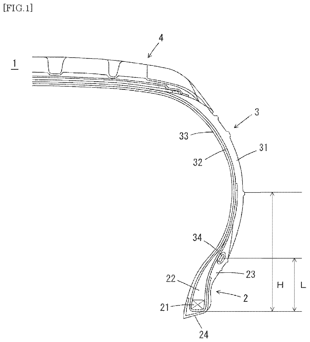
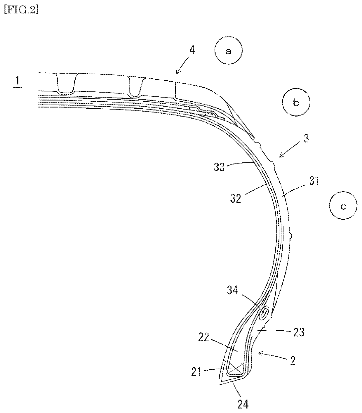
Provided is a tire structure technology with which sufficient reading performance can be maintained even when a tire having an electronic component provided therein is caused to drive under high speed and severe handling. A pneumatic tire in which an electronic component is provided farther outward in a tire axial direction than a carcass, and in which the tanδ(1)50° C. and tanδ(1)150° C. of a first rubber member, and the tanδ(2)50° C. and tanδ(2)150° C. of a second rubber member, satisfy the following formula, where the first rubber member is a tire rubber member that has the greatest E* at 50° C. among tire rubber members positioned outward from the electronic component in the tire axial direction, and the second rubber member is a tire rubber member that has the greatest E* at 50° C. among tire rubber members positioned inward from the electronic component in the tire axial direction.
(tanδ(1)50° C.+tan δ(2)50° C. )−(tanδ(1)150° C.tanδ(2)150° C.)≤0.08

Description

TECHNICAL FIELD[0001]The present invention relates to a pneumatic tire in which an electronic component such as RFID is provided inside.BACKGROUND ART[0002]In recent years, in order to monitor various data such as the internal pressure, temperature and rotational speed of pneumatic tires (hereinafter, also simply referred to as “tires”) to improve safety, maintainability, etc. while the vehicle is traveling, it has been proposed that an electronic component such as transponder for RFID (Radio Frequency Identification) (hereinafter, also simply referred to as “RFID”) for recording the data is to be attached to a tire.[0003]The transponder is a small, lightweight electronic component consisting of a semiconductor chip with a transmitter / receiver circuit, a control circuit, a memory, etc., and an antenna. As the transponder, battery-less one is often used which can transmit various data as response radio waves when it receives an inquiry radio wave, which is used as electrical energy.[...

Claims


Application Information

Patent Timeline
Patent Type & Authority Applications(United States)
IPC IPC(8): B60C19/00
CPCB60C19/00G06K19/07764B60C2019/004B60C2015/0614B60C2013/006B60C15/0603
Inventor YOSHIZUMI, TAKUMANAKAJIMA, HIROKI
Owner SUMITOMO RUBBER IND LTD
Why Eureka
Try Eureka