Seal and Plumbing Fitting

a technology for plumbing fittings and sealing, which is applied in the direction of multiple way valves, mechanical equipment, engine components, etc., can solve the problems of easy damage, difficult to move said parts as required, and substantial frictional resistance, so as to reduce the risk of introducing complications, increase time and cost efficiency, and improve time and cost efficiency

Pending Publication Date: 2021-03-11
PEGLER YORKSHIRE GRP LTD
View PDF6 Cites 2 Cited by
  • Summary
  • Abstract
  • Description
  • Claims
  • Application Information

AI Technical Summary

Benefits of technology

[0045]Accordingly, in embodiments, in the third position the mechanism can be maintained or repaired without isolating the plumbing fitting from the plumbing system to which it is connected. This can be more time and cost efficient than isolating the plumbing fitting, e.g. using valves on pipes upstream and / or downstream from the plumbing fitting. Also, in embodiments, in the third position the mechanism can be accessed for maintenance or repair without additional plumbing tools and / or without trained personnel. This can increase time and cost efficiency relative to known plumbing fittings. Moreover, in embodiments, the mechanism can be maintained or repaired using fewer steps than are required to maintain or repair known plumbing fittings. This can reduce the risk of introducing complications to the plumbing system to which the plumbing fitting is connected. Also, by virtue of the bypass position via the inner body, there is reduced risk of inadvertent fluid egress between the outer body and the inner body and the plumbing fitting can be flushed, not just isolated.
[0046]Thus, embodiments of the present invention provide a plumbing fitting that can be more conveniently and efficiently maintained or repaired than, and is less prone to inadvertent fluid egress relative to, known plumbing fittings.

Problems solved by technology

A problem with known seals is that they can impart a substantial amount of frictional resistance to parts of a plumbing fitting which are movable relative to each other and between which the seal is located.
Consequently, it can be difficult to move said parts as required.
Another problem with known seals is that they can be easily damaged by moving parts of a plumbing fitting relative to each other.
In particular, such relative movement can crack or deteriorate the seal, which can impair the performance of the plumbing fitting.
Yet another problem with known seals is that they can be difficult to assemble, which can result in protracted assembly times, incorrect assembly and impaired performance.

Method used


Image

  • Seal and Plumbing Fitting
  • Seal and Plumbing Fitting
  • Seal and Plumbing Fitting

Examples


Embodiment Construction

[0083]In order that the invention may be more clearly understood one or more embodiments thereof will now be described, by way of example only, with reference to the accompanying drawings, of which:

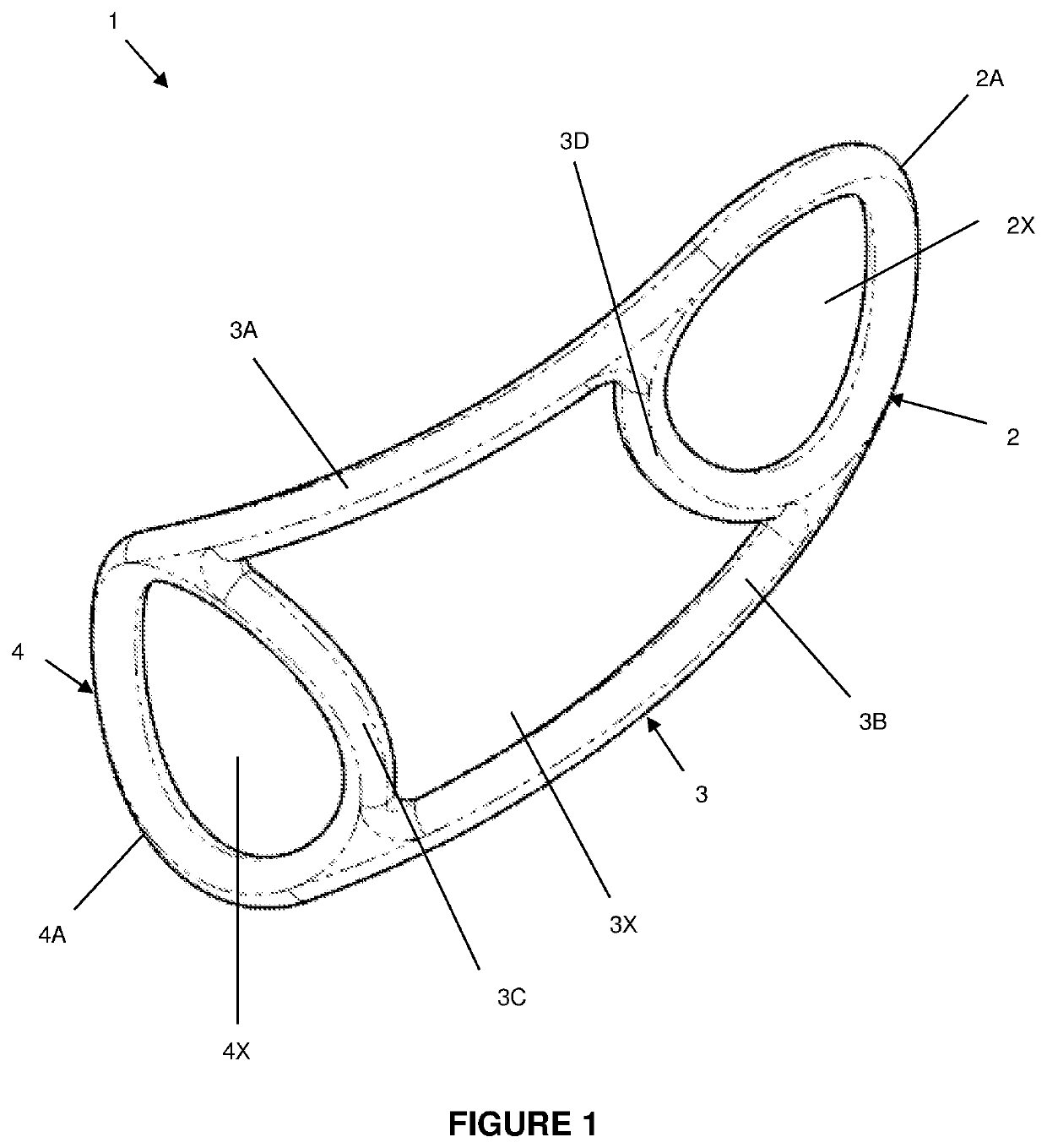
[0084]FIG. 1 shows a seal according to the invention;

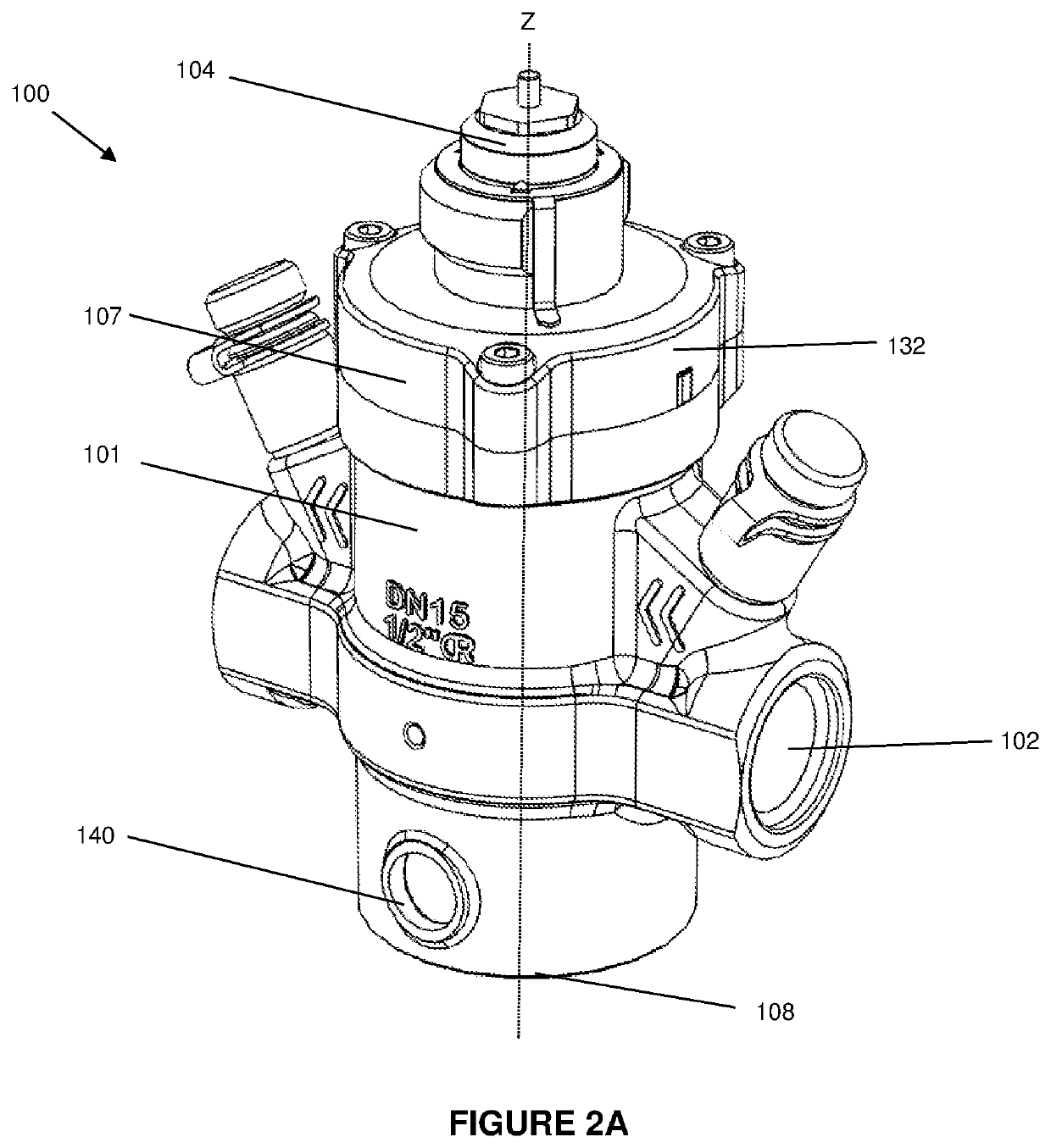
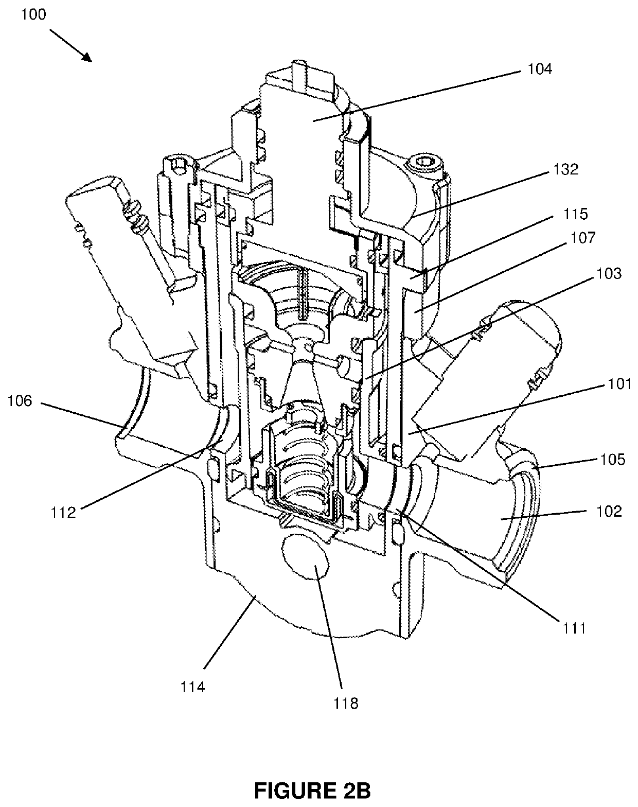
[0085]FIG. 2A shows a perspective view of a plumbing fitting comprising the seal of FIG. 1, wherein the plumbing fitting is configured in an operational position;

[0086]FIG. 2B shows a cross sectional view of the plumbing fitting of FIG. 2A;

[0087]FIG. 3A shows a perspective view of the plumbing fitting of FIG. 2A, wherein the plumbing fitting is configured in an isolation position;

[0088]FIG. 3B shows a cross sectional view of the plumbing fitting of FIG. 3A;

[0089]FIG. 4A shows a perspective view of the plumbing fitting of FIG. 2A, wherein the plumbing fitting is configured in a bypass position;

[0090]FIG. 4B shows a cross sectional view of the plumbing fitting of FIG. 4A;

[0091]FIG. 5 shows an alternative view of the plumbing fitting of FI...


PUM


Abstract

A seal for a plumbing fitting includes two or more respective apertured sealing portions. Each apertured sealing portion independently includes one or more edge portions enclosing an aperture therebetween. The apertured portions are integrally formed.

Description

TECHNICAL FIELD OF THE INVENTION[0001]The present invention relates to a seal, a plumbing fitting comprising a seal, and methods and uses relating thereto.BACKGROUND TO THE INVENTION[0002]It is known to use seals in plumbing fittings, e.g. valves such as pressure independent control valves (PICVs), to prevent inadvertent fluid egress between parts of the plumbing fitting. Such seals are often provided in the form of an O-ring, or an arrangement of respective O-rings.[0003]For example, a known PICV comprises an arrangement of respective O-ring seals. The PICV has a housing in which a cartridge is received, the housing and the cartridge each having an inlet and an outlet. The O-ring seals are independently arranged around an outer surface of the cartridge so as to encircle the cartridge. This arrangement of O-ring seals is, in general terms, intended to prevent inadvertent fluid egress between the housing and the pod.[0004]A problem with known seals is that they can impart a substanti...

Claims


Application Information

Patent Timeline
Patent Type & Authority Applications(United States)
IPC IPC(8): F16J15/02E03C1/02
CPCF16J15/022E03C1/021F16K5/0478F16K11/0856F16J15/106F16J15/061F16K11/078F16K5/0407F16K31/5284E03C1/02E03C1/12F16K5/00E03C1/01
Inventor WHITELEY, PAUL NICHOLASWHITE, SAMUEL CHARLES
Owner PEGLER YORKSHIRE GRP LTD
Why Eureka
Try Eureka