
System and method for vehicle routing

a vehicle routing and system technology, applied in the field of automatic systems and methods for optimal vehicle routing, can solve the problems of affecting routing, affecting network characteristics, and reducing total operating costs and total costs, so as to reduce total operating costs and reduce total operating costs. the effect of unit operating costs

Pending Publication Date: 2021-03-11
MORGAN STATE UNIVERSITY
View PDF3 Cites 4 Cited by
  • Summary
  • Abstract
  • Description
  • Claims
  • Application Information

AI Technical Summary

Benefits of technology

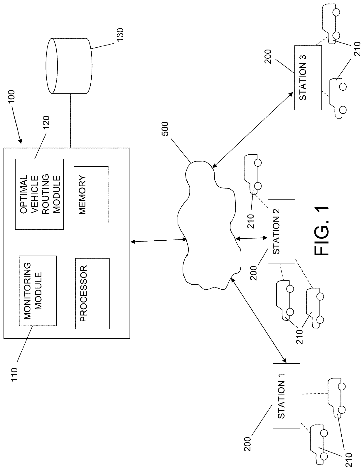
The invention is an automated system and method for routing transport vehicles in a multi-station transit network. The system and method aim to minimize total costs associated with transport, including passengers' travel costs and operating costs. It can reroute and relocate feeder buses when an optimal bus routing is not feasible with the currently available buses at certain stations in the network. The system uses flexible routing, which means lower unit operating costs not only decrease total operating costs and total costs, but also can affect routing and impact network characteristics. It can generate optimal flexible demand responsive feeder transit networks with various unit transit operating costs using the automated system and method described herein. Overall, the system and method allow for efficient and cost-effective transportation in a multi-station transit network.

Problems solved by technology

Unlike fixed route mass transit, small vehicle demand responsive service uses flexible routing, which means lower unit operating costs not only decrease total operating costs and total costs, but also can affect routing and impact network characteristics.

Method used


Image

  • System and method for vehicle routing
  • System and method for vehicle routing
  • System and method for vehicle routing

Examples


Embodiment Construction

[0025]The invention summarized above may be better understood by referring to the following description, claims, and accompanying drawings. This description of an embodiment, set out below to enable one to practice an implementation of the invention, is not intended to limit the preferred embodiment, but to serve as a particular example thereof. Those skilled in the art should appreciate that they may readily use the conception and specific embodiments disclosed as a basis for modifying or designing other methods and systems for carrying out the same purposes of the present invention. Those skilled in the art should also realize that such equivalent assemblies do not depart from the spirit and scope of the invention in its broadest form.

[0026]Descriptions of well-known functions and structures are omitted to enhance clarity and conciseness. The terminology used herein is for the purpose of describing particular embodiments only and is not intended to be limiting of the present discl...


PUM


Abstract

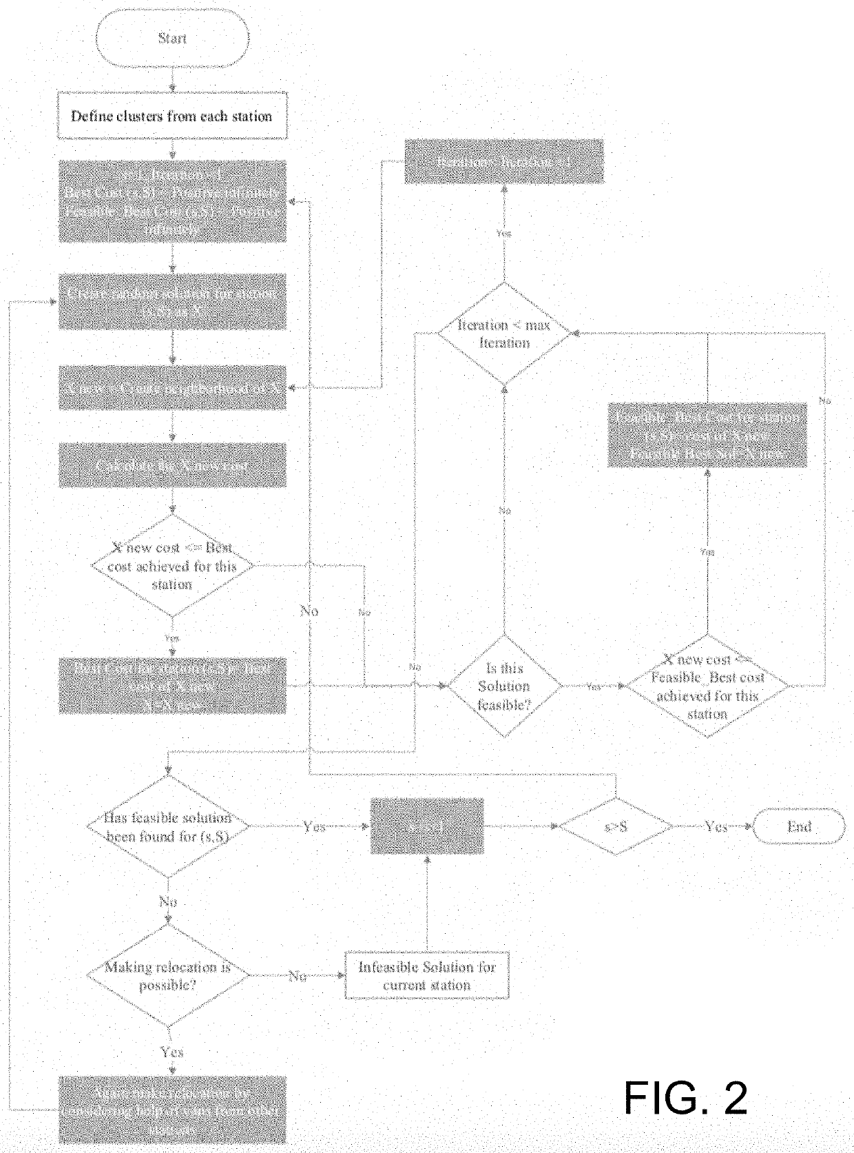
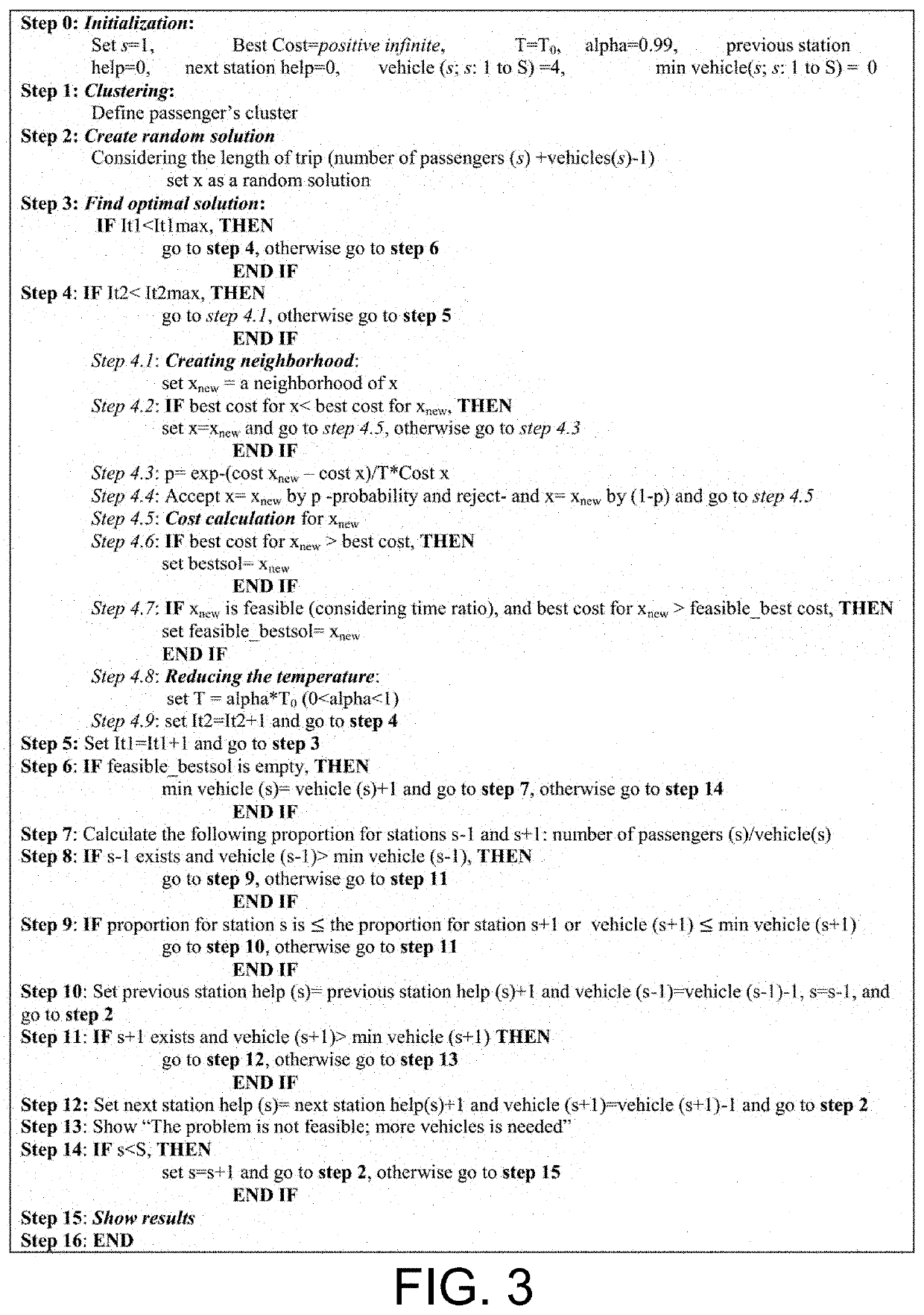
Disclosed is a system and method for the automated routing of people and materials from one location to another based on automated vehicle technology as it applies to bus transit, ridesharing and car sharing, and on multiple modes of delivery including rail, water, road and air. An optimal transit algorithm is employed that uses Degree of Circuity (DOC) and Maximum Degree of Circuity (Max DOC) to better refine transit network design and scheduling. The given Max DOC and computed shortest travel times are used to define the maximum acceptable travel time for each passenger or package (i.e., “transport item” as used herein). Using those maximum acceptable travel times for passengers and / or packages as constraints, optimal routings are developed for each primary transport hub, such as a train station, using the Simulated Annealing (SA) algorithm. The SA algorithm may be used as a basis for optimal flexible feeder bus routing, which considers relocation of buses for multiple primary transport hubs, such as multiple train stations, and multiple primary transport vehicles, such as multiple trains at each such station.

Description

CROSS REFERENCE TO RELATED APPLICATIONS[0001]This application is based upon and claims the benefit of U.S. Provisional Application No. 62 / 898,111 titled “Optimal Automated Demand Responsive Feeder Transit Operation Method,” filed with the United States Patent & Trademark Office on Sep. 10, 2019, the specification of which is incorporated herein by reference in its entirety.GOVERNMENT LICENSE RIGHTS[0002]Portions of the invention described herein were made with government support under Contract No. 69A43551747123 awarded by the U.S. Department of Transportation. The U.S. government may have certain rights in the invention.FIELD OF THE INVENTION[0003]This invention is directed to automated systems and methods for optimal routing of vehicles for transporting transport items (such as human passengers, packages, parcels, and the like), and more particularly to an automated system and method for the routing of vehicles in a transportation system comprising multiple modes of transportation...

Claims


Application Information

Patent Timeline
Patent Type & Authority Applications(United States)
IPC IPC(8): G01C21/34G01C21/36G06Q50/30G06Q10/06G06Q10/04
CPCG01C21/3453G01C21/362G06Q10/06312G06Q10/06315G06Q10/047G06Q50/30G01C21/3423G06Q50/40
Inventor LEE, YOUNG-JAENICKKAR, AMIRREZA
Owner MORGAN STATE UNIVERSITY
Learn More