
Structural design systems and methods for optimizing equipment selection in floorplans using modeling and simulation

a technology of structural design and equipment selection, applied in the field of structural design systems and methods, can solve the problems of imposing significant challenges, unable to use conventional techniques for ensuring equipment coverage, and insufficient assurance of conventional selection methods

Inactive Publication Date: 2021-03-11
BEAMUP LTD
View PDF0 Cites 8 Cited by
  • Summary
  • Abstract
  • Description
  • Claims
  • Application Information

AI Technical Summary

Benefits of technology

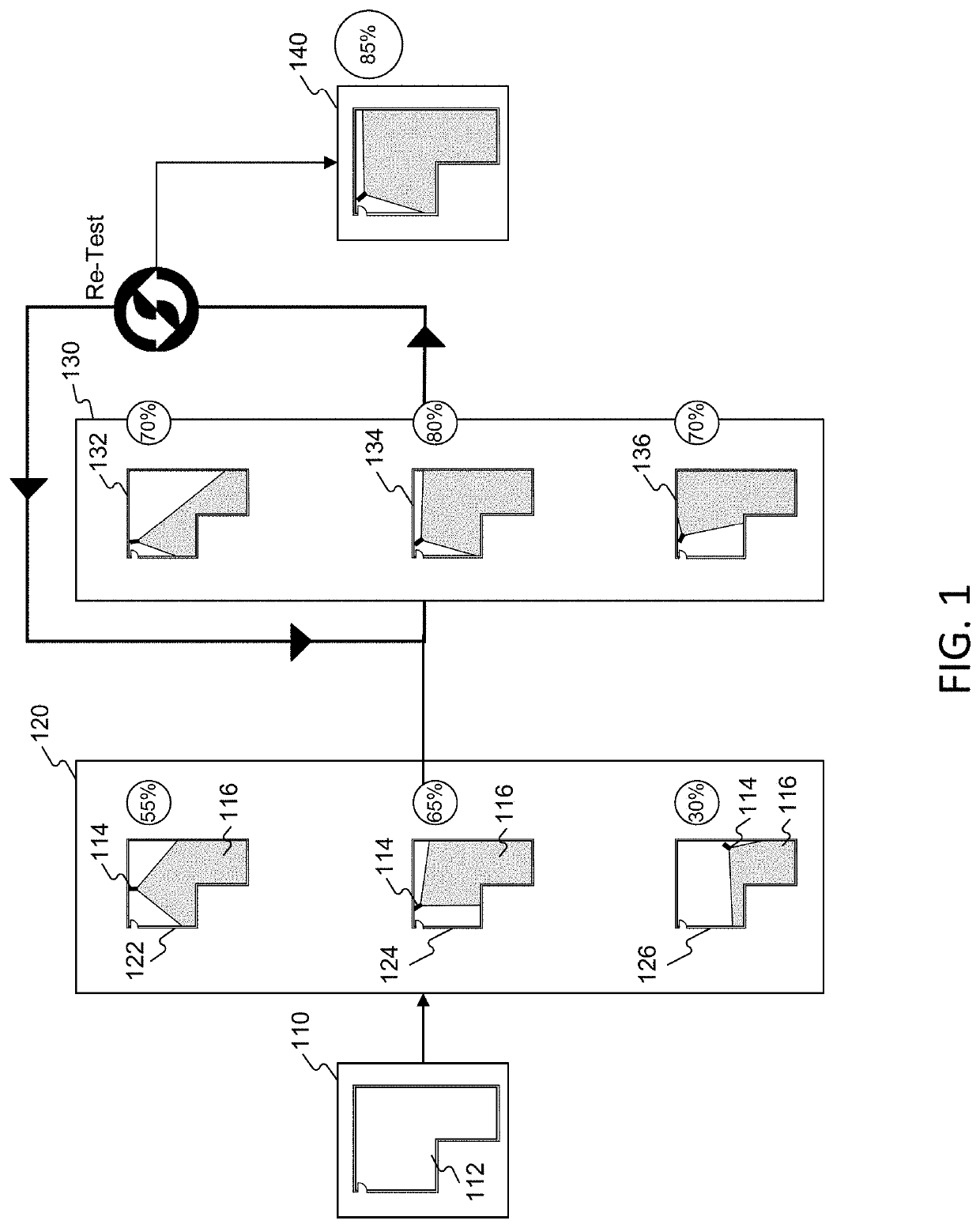
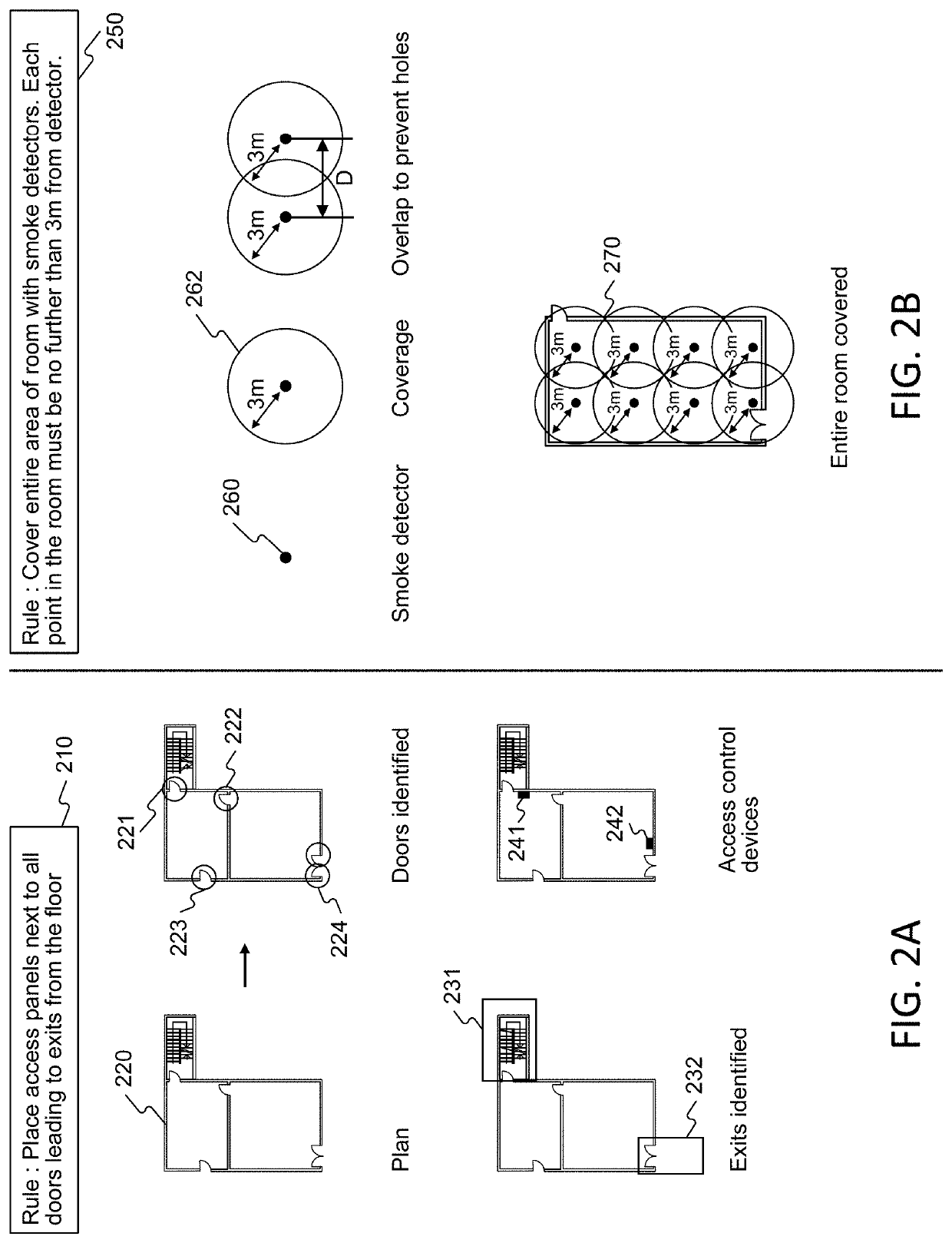
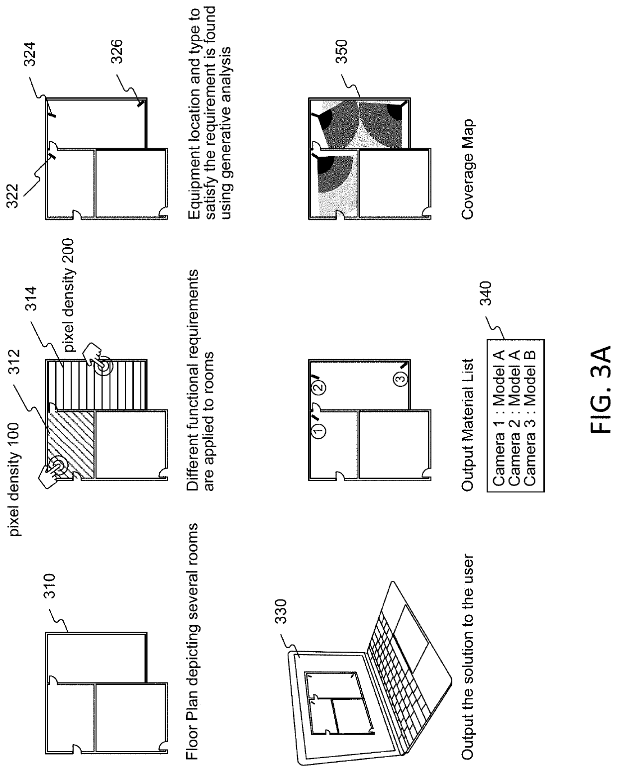
The patent is about a system and method for selecting equipment for buildings. It involves accessing floor plans and functional requirements for different rooms, analyzing the floor plans to determine room features, and then using those features to determine which equipment to use in each room. The system generates a manufacturer dataset that includes a room identifier, an equipment identifier, and the customized equipment configuration, making it easy for manufacturers to customize equipment for each room and package it accordingly. The technical effect of this patent is to provide a more efficient and customized approach to selecting equipment for buildings.

Problems solved by technology

Conventional approaches to selecting equipment may not adequately ensure that each space in every room in a floor plan that should be covered is in fact covered.
Constraints on designers and drafters make it difficult if not impossible to use conventional techniques for ensuring equipment coverage.
Additionally, the interconnectivity of multiple complex systems may impose significant challenges when attempting to select equipment to improve performance or coverage.
As a result, conventional approaches may lead to inefficiencies, high costs, sub optimal solutions, or rigid plans that may not satisfy coverage needs.

Method used


Image

  • Structural design systems and methods for optimizing equipment selection in floorplans using modeling and simulation
  • Structural design systems and methods for optimizing equipment selection in floorplans using modeling and simulation
  • Structural design systems and methods for optimizing equipment selection in floorplans using modeling and simulation

Examples


Embodiment Construction

[0092]In architectural planning, selecting the appropriate specifications and locations for equipment to be used in many rooms in a floor plan can be a daunting task. For example, each room may have multiple functional requirements that may affect the selection and placement of equipment within the room. Further, there may be thousands of possible combinations of equipment specifications and placement locations, each with varying degrees of conformance to the functional requirements.

[0093]Therefore, there is a need for unconventional approaches that enable users to input functional specifications for multiple rooms into a system configured to run a series of simulations to automatically suggest equipment and equipment placement within the rooms.

[0094]The disclosed methods and systems are directed to provided new and unconventional methods of selective simulation of equipment coverage in a floor plan. Conventional approached to selecting equipment in a floor plan may be unable to gen...


PUM


Abstract

Systems and methods for selecting equipment models and optimizing placement of equipment in floor plans are disclosed. Operations may include access a floor plan demarcating a plurality of rooms, where the floor plan includes a plurality of equipment symbols, enable a user to select an equipment symbol for analysis, access functional requirements for a set of rooms in the plurality of rooms containing the instances of the selected equipment symbols, access equipment technical specifications to identify equipment technical specifications associated with the functional requirements, perform a generative analysis on the identified equipment technical specifications within identified walls of each room in the set of rooms to select an equipment model that at least partially conforms to the functional requirements, update the floor plan by associating the selected equipment model with the instances of the selected equipment symbols, and output a bill of material based on the updated floor plan.

Description

CROSS-REFERENCE TO RELATED APPLICATIONS[0001]This application is based on and claims benefit of priority of U.S. Provisional Patent Application No. 62 / 897,159 filed Sep. 6, 2019; U.S. Provisional Patent Application No. 62 / 940,040 filed Nov. 25, 2019; U.S. Provisional Patent Application No. 62 / 980,932 filed Feb. 24, 2020; and U.S. Provisional Patent Application No. 63 / 016,131 filed Apr. 27, 2020. The contents of the foregoing applications are incorporated herein by reference in their entirety.BACKGROUNDTechnical Field[0002]The disclosed embodiments generally relate to structural design systems and methods for selecting equipment models and optimizing placement of equipment in floor plans.Background Information[0003]Some disclosed methods and systems are directed to providing new and unconventional methods for selectively simulating equipment coverage in a floor plan. Building planners may seek to ensure that a floor plan is sufficiently covered by lights, cameras, motion detectors, o...

Claims


Application Information

Patent Timeline
Patent Type & Authority Applications(United States)
IPC IPC(8): G06F30/12G06F30/13G06F30/18G06F30/27G06Q10/08
CPCG06F30/12G06F30/13G06Q10/0875G06F30/27G06F30/18G06F30/20G06N5/025G06F2113/14G06F2113/16G06N20/00G06F3/0484G06V10/235G06V10/44
Inventor LEVY, STEPHANESEGEV, TOMAUSTERN, GUYGOYHMAN, YONI
Owner BEAMUP LTD
Learn More