Lighting junction box with assembly for hanging

a junction box and assembly technology, applied in the field of junction boxes, can solve the problems of complex manufacture and installation of recessed lighting, and achieve the effects of facilitating installation and/or mounting, facilitating vertical adjustment, and facilitating the way existing electrical connections are mad

Active Publication Date: 2021-03-18
AMP PLUS
View PDF4 Cites 11 Cited by
  • Summary
  • Abstract
  • Description
  • Claims
  • Application Information

AI Technical Summary

Benefits of technology

[0011]It is an objective of the present invention to provide a lighting-junction-box that is both substantially octagonal in its upper regions and cylindrical in its lower regions, as the octagonal region mimics preexisting octagonal junction boxes which facilitates how existing electrical connections are made to preexisting octagonal junction boxes; while the cylindrical region mimics lighting hardware where the lighting hardware elements (e.g., light emitters, reflectors, and / or trims) are often cylindrical and / or conical in shape.
[0012]It is another objective of the present invention to facilitate ease of installing and / or mounting the lighting-junction-box into ceilings by providing a means of vertical adjustment between the lighting-junction-box and hanger-bars.
[0013]It is yet another objective of the present invention to provide external vertical markings on the lighting-junction-box to facilitate the vertical adjustments when installing and / or mounting (often in a recessed manner with respect to a given ceiling).

Problems solved by technology

The manufacture and installation of recessed lighting is complicated by the required adherence to building codes and regulations.

Method used


Image

  • Lighting junction box with assembly for hanging
  • Lighting junction box with assembly for hanging
  • Lighting junction box with assembly for hanging

Examples


Embodiment Construction

[0079]The present patent application is a continuation-in-part (CIP) of U.S. non-provisional patent application Ser. No. 16 / 417,546 filed on May 20, 2019, and claims priority to said U.S. non-provisional patent application under 35 U.S.C. § 120. Patent application Ser. No. 16 / 417,546 is incorporated herein by reference in its entirety as if fully set forth below.

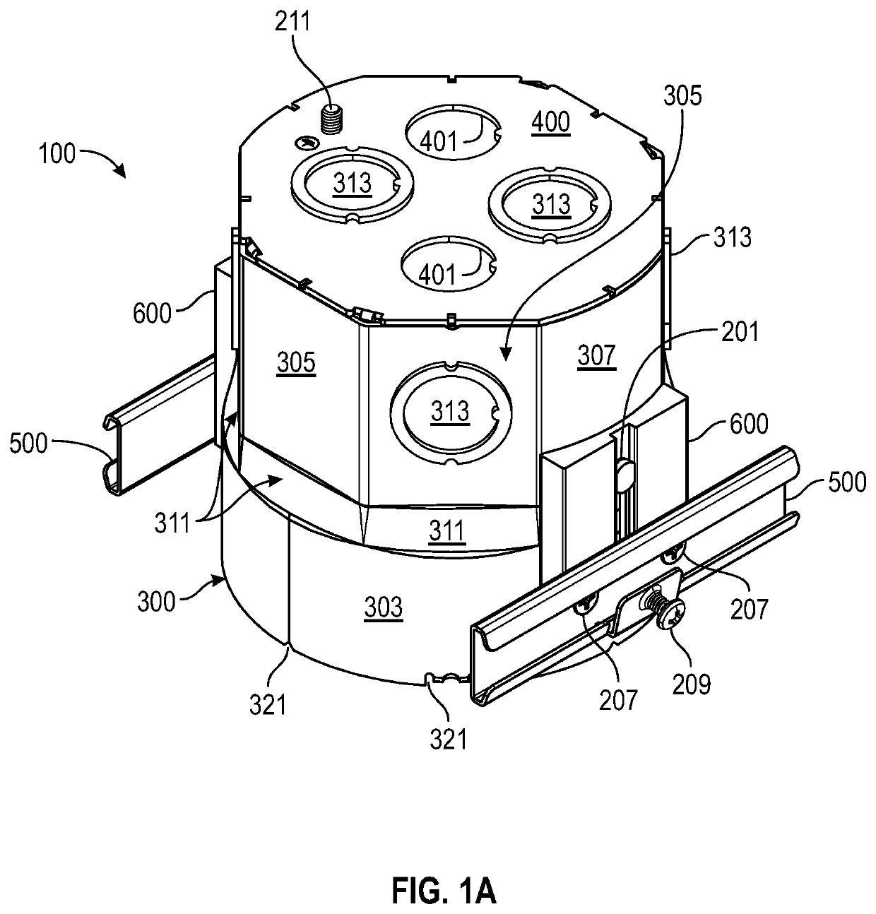
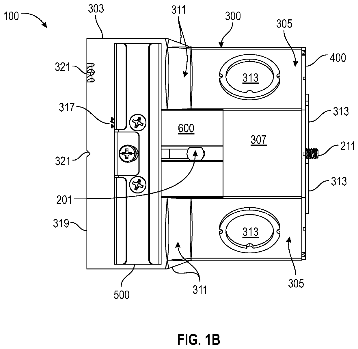
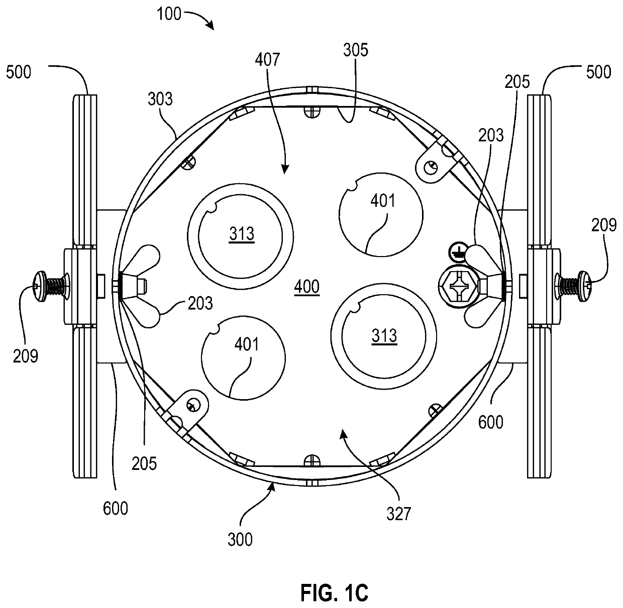
[0080]Note, with respect to differences between the present patent application and the parent patent application (with patent application Ser. No. 16 / 417,546), at least some differences may be as follows: (a) junction-box 300 (as disclosed herein) may have no slots, such as slots 128 of patent application Ser. No. 16 / 417,546; slots 128 of patent application Ser. No. 16 / 417,546 are replaced with holes 309 in the present patent application; (b) adjusting-plate 600 (as disclosed herein) may have no holes for a carriage-bolts as bracket 154 of patent application Ser. No. 16 / 417,546 does have; instead, adjusting-plate 600 may hav...


PUM


Abstract

A lighting-junction-box may have sidewalls that bound a cavity. The cavity may be con-figured to receive an electronic component that is configured to emit light. The sidewalls may be divided into an upper-portion and a lower-portion. The lower-portion may be substantially cylindrical in shape. The upper-portion may be substantially octagonal in shape, except that two of the eight faces may be curved, while the remaining six faces may be flat and planar. The two curved faces may be oppositely disposed from each other. The two curved faces may have holes for receiving carriage-bolts for attaching adjusting-plates to the lighting-junction-box. Below the holes of the two curved faces on the lower-portion may be external-length-gauges to assist with mounting the lighting-junction-box. The adjusting-plates may have slots for receiving the carriage-bolts and to allow for vertical adjustment of the lighting-junction-box with respect to the adjusting-plates.

Description

PRIORITY NOTICE[0001]The present patent application is a continuation-in-part (CIP) of U.S. non-provisional patent application Ser. No. 16 / 417,546 filed on May 20, 2019, and claims priority to said U.S. non-provisional patent application under 35 U.S.C. § 120. The above-identified patent application is incorporated herein by reference in its entirety as if fully set forth below.TECHNICAL FIELD OF THE INVENTION[0002]The present invention relates in general to junction boxes and more specifically to lighting junction boxes with assemblies for attaching to hanger bars that slidingly adjustable.COPYRIGHT AND TRADEMARK NOTICE[0003]A portion of the disclosure of this patent application may contain material that is subject to copyright protection. The owner has no objection to the facsimile reproduction by anyone of the patent document or the patent disclosure, as it appears in the Patent and Trademark Office patent file or records, but otherwise reserves all copyrights whatsoever.[0004]Ce...

Claims


Application Information

Patent Timeline
Patent Type & Authority Applications(United States)
IPC IPC(8): F21V15/01F21V23/06F21V21/34
CPCF21V15/01F21V21/34F21V23/06F21S8/026F21V21/048F21Y2115/10H02G3/125H02G3/20H02G3/086H02G3/12H02G3/08
Inventor COHEN, BRANDON
Owner AMP PLUS
Why Eureka
Try Eureka