Check patentability & draft patents in minutes with Patsnap Eureka AI!

Device and method for detecting a foreign object in a wireless power transfer system

Pending Publication Date: 2021-03-18
GENERAL ELECTRIC CO
View PDF9 Cites 2 Cited by
  • Summary
  • Abstract
  • Description
  • Claims
  • Application Information

AI Technical Summary

Benefits of technology

This patent is about a device that detects foreign objects in a wireless power transfer system. The device includes an injection unit that receives a DC power signal and generates a first AC power signal with a first frequency based on the received DC power signal. This first AC power signal is then sent to an array of coils that generate an electromagnetic field. The detection unit measures a parameter of the DC power signal and the first AC power signal, and detects any foreign objects within the electromagnetic field based on any changes in the parameter. The wireless power transfer system also includes a power drive unit that generates a second AC power signal with a second frequency. The second AC power signal is sent to a primary coil that generates a second electromagnetic field. The control unit sends a termination signal to the power drive unit to stop transmitting the second AC power signal if a foreign object is detected. The invention helps to improve the safety and reliability of wireless power transfer systems.

Problems solved by technology

However, due to environmental impact, such connectors and wires may be adversely affected.
Hence, establishing a physical connection between the power source and the batteries in the vehicle may involve cumbersome safety measures.
Also, such a power transfer system may become bulkier and heavier compared to the contactless power transfer system.
As a result, the foreign object may be substantially heated up and affect the components in the charging device.
Also, there is an additional power loss in the system due to power consumption by the foreign object, which in-turn affects the efficiency of the power transfer system.

Method used


Image

  • Device and method for detecting a foreign object in a wireless power transfer system
  • Device and method for detecting a foreign object in a wireless power transfer system
  • Device and method for detecting a foreign object in a wireless power transfer system

Examples


Embodiment Construction

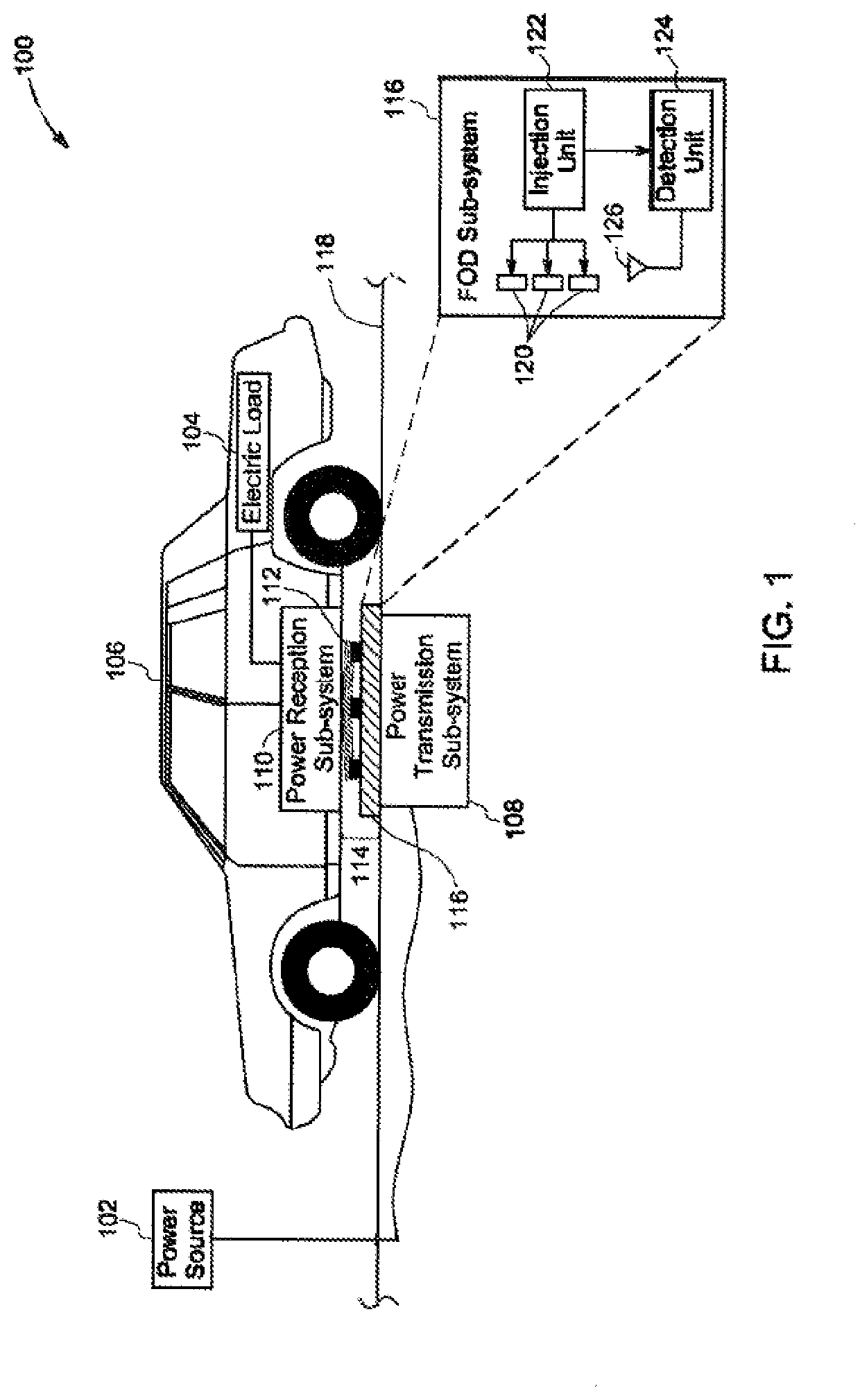
[0020]As will be described in detail hereinafter, embodiments of a device and a method for detecting a foreign object in a wireless power transfer system are disclosed. In particular, embodiments of the device and the method discloses detection of the foreign object using low power signals and without affecting power transfer in the wireless power transfer system. Also, the device and the method ensures that the wireless power transfer system is compliant to society of automotive engineers (SAE) standards. Moreover, the foreign object is detected with good degree of sensitivity of detection.

[0021]Unless defined otherwise, technical and scientific terms used herein have the same meaning as is commonly understood by one of ordinary skill in the art to which this specification belongs. The terms “first”, “second”, and the like, as used herein do not denote any order, quantity, or importance, but rather are used to distinguish one element from another. The use of “including”, “comprisin...


PUM


Abstract

A device for detecting a foreign object (112) in a WPT system is disclosed. The device includes an injection unit (122) to receive a DC power signal and generate a first AC power signal having a first frequency. Also, the device includes an array of coils (120) to receive the first AC power signal having the first frequency and generate a first electromagnetic field at the first frequency. Further, the device includes a detection unit (124) to measure a parameter of at least one of the DC power signal received by the injection unit (122) and the first AC power signal generated by the injection unit (122), and detect the foreign object (112) within the first electromagnetic field based on a change in the parameter of at least one of the DC power signal and the first AC power signal across at least one of the array of coils (120).

Description

BACKGROUND[0001]Embodiments of the present invention relate generally to a wireless power transfer system and more particularly to a device and a method for detecting a foreign object in the wireless power transfer system.[0002]An electric vehicle or a hybrid vehicle includes one or more batteries that supply electric power to drive the vehicle. For example, the batteries supply energy to an electric motor to drive a shaft in the vehicle, which in turn drives the vehicle. The batteries are used for supplying the power and hence may be drained and need to be charged from an external power source.[0003]In general, power transfer systems are widely used to transfer power from a power source to one or more electric loads, such as for example, the batteries in the vehicle. Typically, the power transfer systems may be contact based power transfer systems or contactless power transfer systems. In the contact based power transfer systems, components, such as plug, socket connectors, and wir...

Claims


Application Information

Patent Timeline
IPC IPC(8): H02J50/60H02J50/10H02J50/40H02J50/80H01F38/14B60L53/124
CPCH02J50/60H02J50/10H02J50/40B60K6/28H01F38/14B60L53/124H02J2310/48H02J50/80B60L53/122Y02T10/70Y02T90/14Y02T10/7072H02J7/00034B60Y2200/91B60Y2200/92B60Y2300/91
Inventor BHAT, SUMA MEMANA NARAYANAARAVIND, DEEPAKKANAKASABAI, VISWANATHANVIJAYAN, PRADEEPBOHORI, ADNAN KUTUBUDDIN
Owner GENERAL ELECTRIC CO
Features
  • R&D
  • Intellectual Property
  • Life Sciences
  • Materials
  • Tech Scout
  • Unparalleled Data Quality
  • Higher Quality Content
  • 60% Fewer Hallucinations
Learn More