Building panel

a technology for building panels and walls, applied in the field of building panels, can solve problems such as the drawbacks of knowledge systems, and achieve the effects of improving sealing, improving moisture control, and facilitating moisture control

Active Publication Date: 2021-03-25
VÄLINGE INNOVATION AB
View PDF2 Cites 11 Cited by
  • Summary
  • Abstract
  • Description
  • Claims
  • Application Information

AI Technical Summary

Benefits of technology

[0006]An overall objective of the present disclosure is to provide a building panel which facilitates improved control of moisture, such as water. Improved moisture control may include not limited to improved sealing between assembled building panels, improved resistance to water penetration through a surface comprising assembled building panels.
[0007]It is a further object to provide a building panel which facilitates alignment of assembled such building panels.
[0008]It is thus a further object of the present invention to provide a building panel which facilitates improved moisture control of a lay of building panels, such as a floating floor. In particular, it is an object to provide a building panel for improving moisture control and / or at least reduce the possibility of water penetration of the T-joints of such floor lay.
[0014]By “decorative surface layer” is meant a surface layer, which is mainly intended to give the floor its decorative appearance. “Wear resistant surface layer” relates to a high abrasive surface layer, which is mainly adapted to improve the durability of the front side. This conclude in that a “decorative wear resistant surface layer” is a layer, which is intended to give the floor its decorative appearance as well as improve the durability of the front side. A surface layer is typically applied to the core.

Problems solved by technology

However, know systems suffer from drawbacks, for example in respect moisture control.

Method used


Image

  • Building panel
  • Building panel
  • Building panel

Examples


Embodiment Construction

[0047]Embodiments of the disclosure will now be described with reference to the appended schematic drawings. It should be emphasised that improved or different functions may be achieved using combinations of the embodiments.

[0048]All embodiments may be used separately or in combinations. Angles, dimensions, rounded parts, spaces between surfaces, etc. are only examples and may be adjusted within the basic principles of the invention.

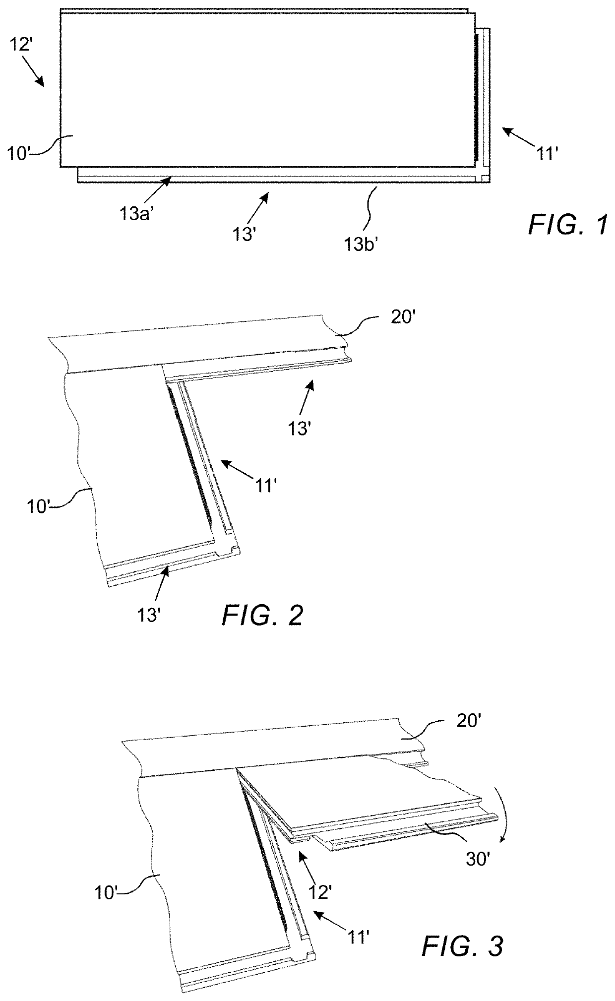
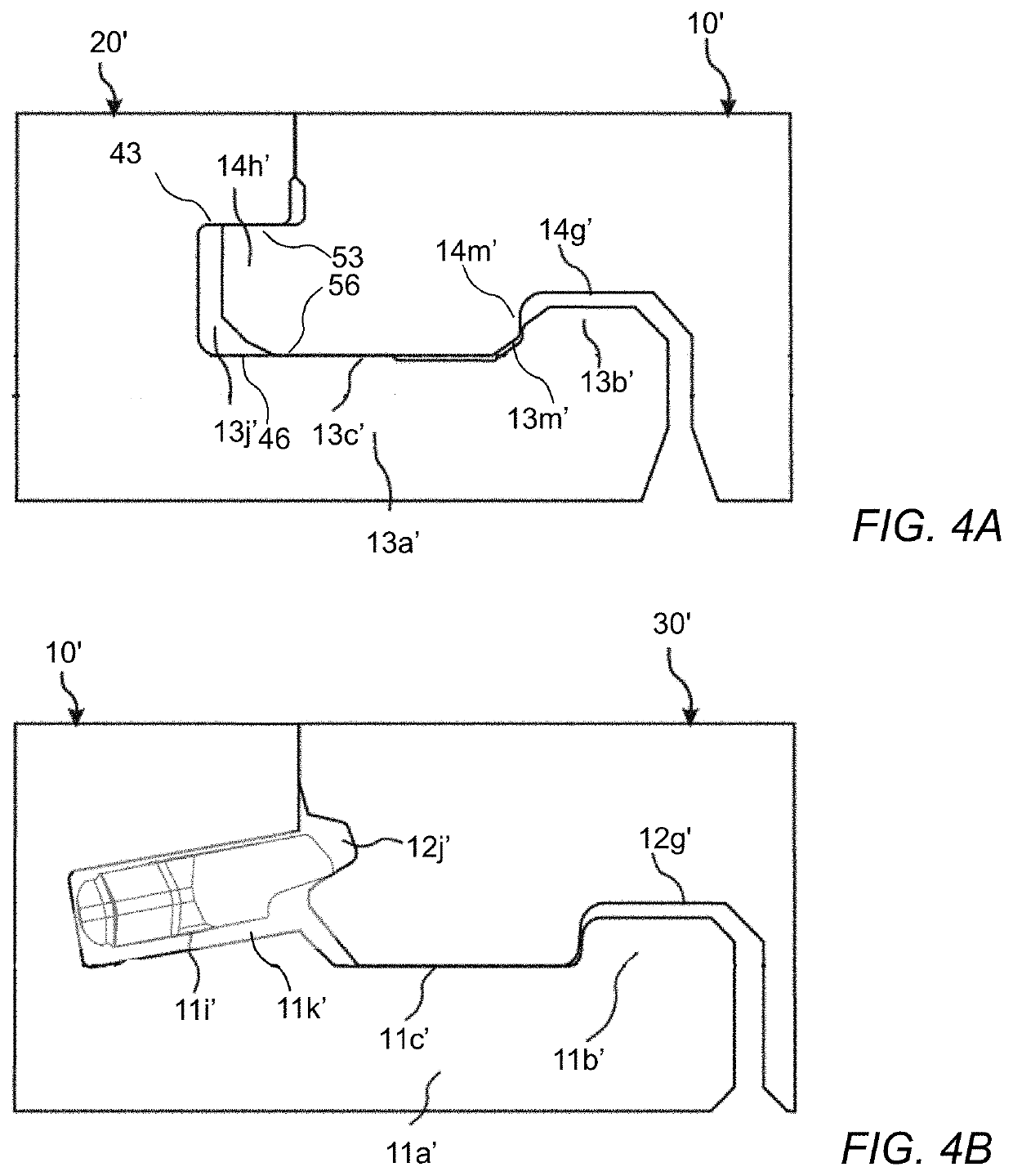
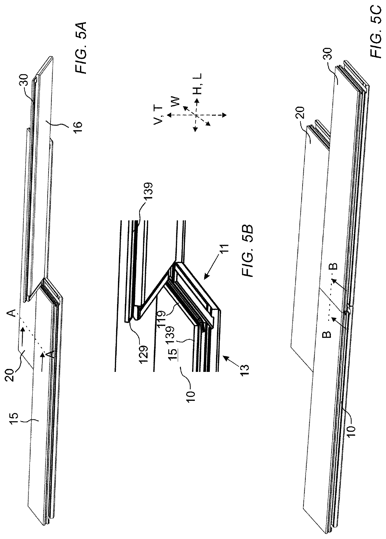
[0049]A known building panel comprising mechanical locking systems is illustrated in FIG. 1.

[0050]A mechanical locking system typically comprises a tongue and a tongue groove for vertical locking and a locking element and a locking groove for horizontal locking. It typically has at least four pairs of active cooperating locking surfaces, two pairs for vertical locking and two pairs for horizontal locking. The locking system comprises several other surfaces, which generally are not in contact with each other and can therefore be produced with considerably...


PUM


Abstract

Building panels, such as a floor panels or wall panels. The panels including a first mechanical locking system at respective parallel and opposite third and fourth edges, such as long edges, configured to cooperate for horizontal and vertical locking between two adjacent building panels, preferably by means of a folding motion. The panels further including a second locking system at respective parallel and opposite first and second edges, such as short edges, configured to cooperate for horizontal and vertical locking of two adjacent building panels. An upper edge portion of one of the third edge or fourth edge, preferably the third edge, includes a first lower lip portion configured to cooperate with a first upper lip portion of an upper edge portion of the other of the third and fourth edge of an adjacent panel when the third and fourth edges are arranged in locking engagement.

Description

CROSS REFERENCE TO RELATED APPLICATIONS[0001]The present application claims the benefit of European Application No. 19199234.6, filed on Sep. 24, 2019. The entire contents of European Application No. 19199234.6 are hereby incorporated herein by reference in their entirety.TECHNICAL FIELD[0002]The disclosure generally relates to the field of building panels.BACKGROUND OF INVENTION[0003]Laminate flooring usually comprise a core of a 6-12 mm fibre board, a 0.2-0.8 mm thick upper decorative surface layer of laminate and a 0.1-0.6 mm thick lower balancing layer of laminate, plastic, paper or like material. A laminate surface comprises melamine-impregnated paper. The most common core material is fibreboard with high density and good stability usually called HDF—High Density Fibreboard. Sometimes also MDF—Medium Density Fibreboard—is used as core.[0004]Laminate floor panels of this type have been joined mechanically by means of so-called mechanical locking systems. These systems comprise l...

Claims


Application Information

Patent Timeline
Patent Type & Authority Applications(United States)
IPC IPC(8): E04F15/02
CPCE04F15/02038E04F2201/0153E04F2201/0138E04F2201/023E04F2201/043E04F2201/0547E04F13/0894B27G13/14B27M3/0066B27M3/06E04F2201/0146E04F2201/0161E04F2201/044
Inventor YLIKANGAS, ROGERNILSSON, ANDERSQUIST, KARL
Owner VÄLINGE INNOVATION AB
Why Eureka
Try Eureka