
Lubricant nozzle for a planetary gear set speed reducer of a turbomachine

a technology of planetary gear set and lubricant nozzle, which is applied in the direction of machines/engines, gearing details, mechanical apparatuses, etc., can solve the problems of difficult to reach the sun gear with oil, disadvantages of the type of reducer, and complex mounting, so as to achieve the effect of optimizing the lubrication of the reducer

Active Publication Date: 2021-03-25
SAFRAN TRANSMISSION SYST
View PDF0 Cites 0 Cited by
  • Summary
  • Abstract
  • Description
  • Claims
  • Application Information

AI Technical Summary

Benefits of technology

The patent describes a new design for a nozzle used in lubrication systems. The design has several advantages over previous versions. First, the nozzle has more material at the level of the oil projection apertures, which results in a boss at the top of the nozzle. This boss guides the oil over a longer distance and makes it closest to the gearings, which improves lubrication. Second, the design has a trapezoidal shape, which reduces the volume of the bosses. This makes it easier to manufacture and removes any unevenness in the mass of the nozzle after production. Lastly, the nozzle has a fixing leg, which simplifies its production and reduces costs.

Problems solved by technology

However, this type of reducer has disadvantages.
One of the problems is linked to the good lubrication of the gearings of the planet gears and of the sun gear.
At a high speed, it is difficult to reach the sun gear with the oil, due to the centrifugation effect.
Another of the problems is linked to the complexity of the mounting.

Method used


Image

  • Lubricant nozzle for a planetary gear set speed reducer of a turbomachine
  • Lubricant nozzle for a planetary gear set speed reducer of a turbomachine
  • Lubricant nozzle for a planetary gear set speed reducer of a turbomachine

Examples


Embodiment Construction

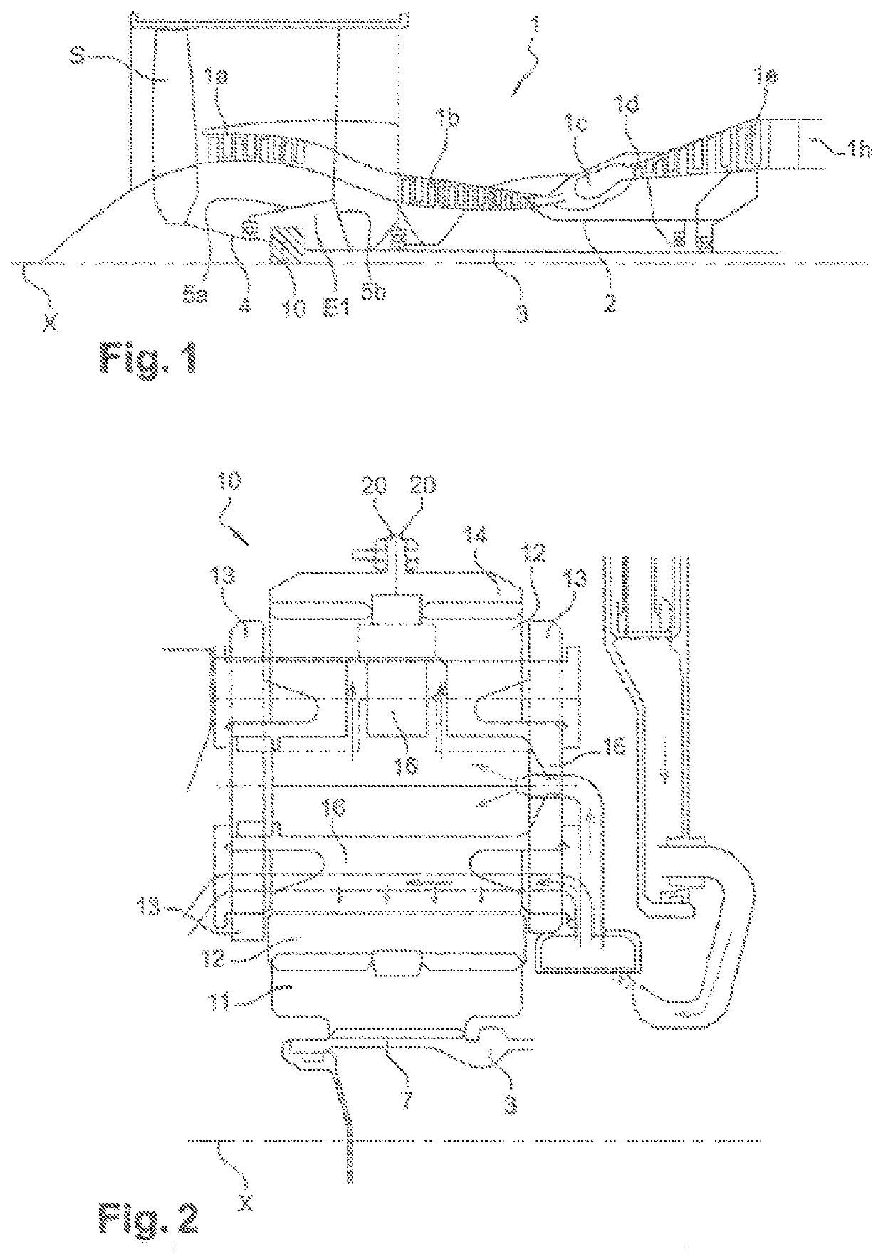
[0040]FIG. 1 shows a turbomachine 1 which comprises, conventionally, a fan propeller S, a low-pressure compressor 1a, a high-pressure compressor 1b, an annular combustion chamber 1c, a high-pressure turbine 1d, a low-pressure turbine 1e and an exhaust pipe 1h. The high-pressure compressor 1b and the high-pressure turbine 1d are connected by a high-pressure shaft 2 and form with it a high-pressure (HP) body. The low-pressure compressor 1a and the low-pressure turbine 1e are connected by a low-pressure shaft 3 and form with it a low-pressure (LP) body.

[0041]The fan propeller S is driven by a fan shaft 4 which is coupled to the LP shaft 3 by means of a planetary gear set reducer 10 represented here schematically.

[0042]The reducer 10 is positioned in the front portion of the turbomachine. A fixed structure schematically comprising, here, an upstream portion 5a and a downstream portion 5b is arranged so as to form an enclosure E1 surrounding the reducer 10. This enclosure E1 is here clos...


PUM


Abstract

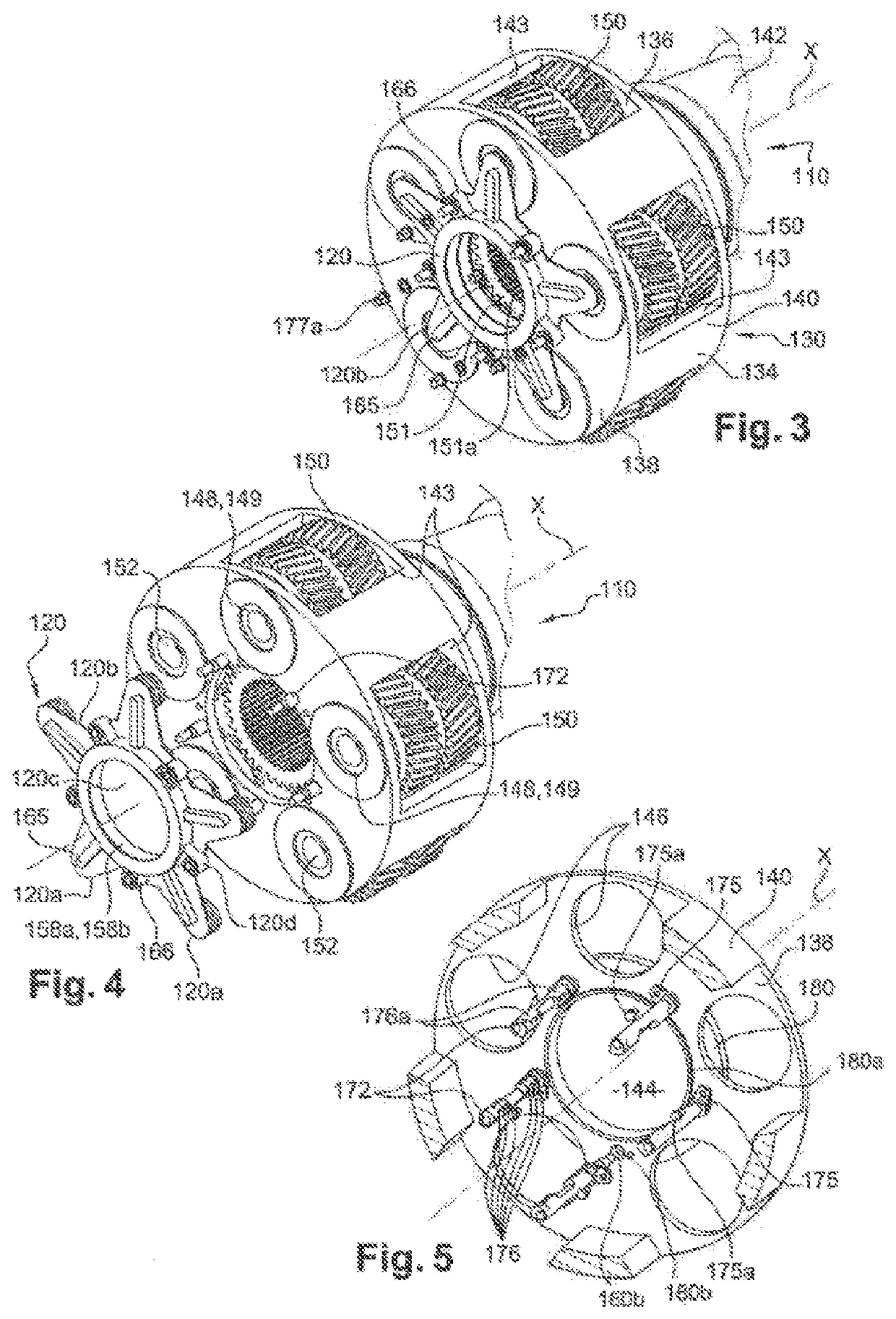
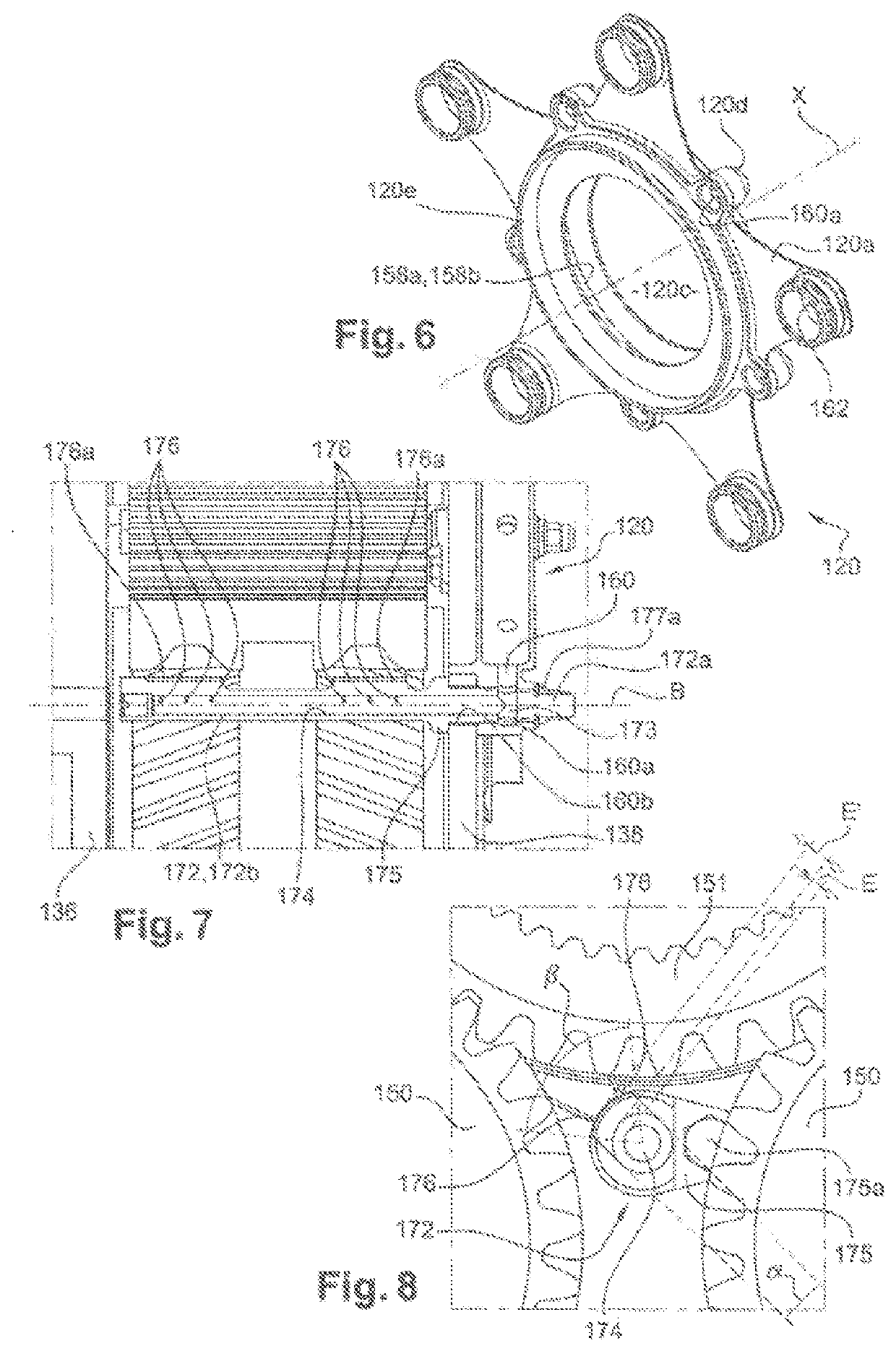
A lubricant nozzle for a planetary gear set speed reducer of a turbomachine, the nozzle having a generally elongate shape and including a body with a longitudinal axis B, the body having a longitudinal inner cavity in fluid communication with a lubricant inlet located at a longitudinal end of the body and with lubricant outlet apertures that are provided in an annular wall of the body and that extend substantially radially relative to the axis B, wherein the apertures are formed in at least one boss of the body, which boss projects radially outwards on the wall and extends, about the axis, at an angular extent that does not exceed 180°.

Description

FIELD OF THE INVENTION[0001]The present invention relates to the field of planetary gear set speed reducers for a turbine engine, in particular of an aircraft, as well as elements which compose a reducer of this type, such as nozzles, a planet gear carrier, an impeller, etc.STATE OF THE ART[0002]The state of the art comprises, in particular, documents WO-A1-2010 / 092263, FR-A1-2 987 416, CN-A-106 594 248, DE-A1-10 2008 004999 and FR-A1-3 041 054.[0003]Current turbomachines, in particular turbomachines comprising one or more propellers blowing a secondary flow, comprise a transmission system, called reducer, to drive this or these propeller(s) at the correct rotation speed from the shaft of the power turbine of the primary body of the engine.[0004]The functioning of the reducers, in particular on turbomachines with a fan propeller with a high dilatation rate, requires a particularly high oil debit, of around 6,000 to 7,000 litres per hour upon take-off, to ensure the lubrication and t...

Claims


Application Information

Patent Timeline
Patent Type & Authority Applications(United States)
IPC IPC(8): F01D25/18F02C7/36
CPCF01D25/18F02C7/36F05D2260/98F05D2220/323F16H57/0482F05D2250/12F05D2250/13F05D2260/40311F05D2250/11F16H57/082F16H57/0409F16H57/0431F16H57/0456F16H57/0457F16H57/0479F16H57/0486F16H57/023
Inventor DI GIOVANNI, JEAN-CHARLES MICHEL PIERREDOMBEK, ALEXIS CLAUDE MICHELMORELLI, BORIS PIERRE MARCEL
Owner SAFRAN TRANSMISSION SYST
Learn More