
Engine cooling device

a cooling device and engine technology, applied in the direction of machines/engines, mechanical devices, cylinders, etc., can solve the problems of long time needed to open the electronic control valve, high hydraulic pressure, and high water jacket hydraulic pressur

Active Publication Date: 2021-03-25
TOYOTA JIDOSHA KK
View PDF0 Cites 2 Cited by
  • Summary
  • Abstract
  • Description
  • Claims
  • Application Information

AI Technical Summary

Benefits of technology

The patent describes an engine cooling device that can protect components in the cooling circuit from hydraulic pressure. This is done by adjusting the position of a valve to control the flow of coolant. The control unit also monitors the supply voltage of the in-vehicle electric power supply and can perform protection control to prevent the hydraulic pressure from exceeding the withstanding pressure limit in any region of the cooling circuit. Additionally, the control unit can perform retreat control to quickly stop the movement of the valve to prevent damage to the cooling circuit components.

Problems solved by technology

Therefore, when the engine rotational speed becomes high with the electronic control valve closed, the hydraulic pressure of the water jacket may become too high.
However, when the supply voltage of an in-vehicle electric power supply drops, the time needed to open the electronic control valve becomes long, and the hydraulic pressure remains high during the time.
Therefore, it may be impossible to sufficiently restrain the hydraulic pressure from rising.
Then, when the hydraulic pressure in any region of the circulation circuit has remained higher than a withstanding pressure limit in the region, namely, an upper limit of the hydraulic pressure permissible in the region as a result, the component members of the circulation circuit cannot withstand the hydraulic pressure, thus causing leakage of the coolant and the like.
Accordingly, when the supply voltage has dropped, the time needed to change the operating position of the valve body in protection control becomes long, and it may become impossible to sufficiently restrain the hydraulic pressure of the circulation circuit from rising.
Therefore, even when the amount of change in the operating position of the valve body in the case where protection control is thereafter performed in response to a rise in engine rotational speed has stopped increasing after reaching a certain amount and the speed of change in the operating position of the valve body has dropped in response to a drop in the supply voltage of the in-vehicle electric power supply, the time needed to change the operating position of the valve body in protection control is unlikely to become long.
Accordingly, with the foregoing engine cooling device, the time needed to restrain the hydraulic pressure of the circulation circuit from rising when the engine rotational speed rises is unlikely to become long, even when the supply voltage of the in-vehicle electric power supply has dropped.
Incidentally, in protection control as described above as well, the hydraulic pressure is insufficiently restrained from rising, unless an appropriate operating position where the withstanding pressure limit rotational speed is equal to or higher than the current engine rotational speed is set as the target rotational position.
Immediately after the startup of the engine, the supply voltage of the in-vehicle electric power supply may temporarily drop due to the consumption of electric power for the startup of the engine.
Therefore, the performance of retreat control is often unnecessary as a measure against the drop in supply voltage at this time.
Therefore, even when the temperature of coolant is low, the speed at which the operating position of the valve body is changed by the actuator is low.
Besides, in the engine mounted on the vehicle, the engine rotational speed may rapidly rise due to a downshift or the like during coasting of the vehicle when the engine is dragged as the wheels rotate.

Method used


Image

  • Engine cooling device
  • Engine cooling device
  • Engine cooling device

Examples


Embodiment Construction

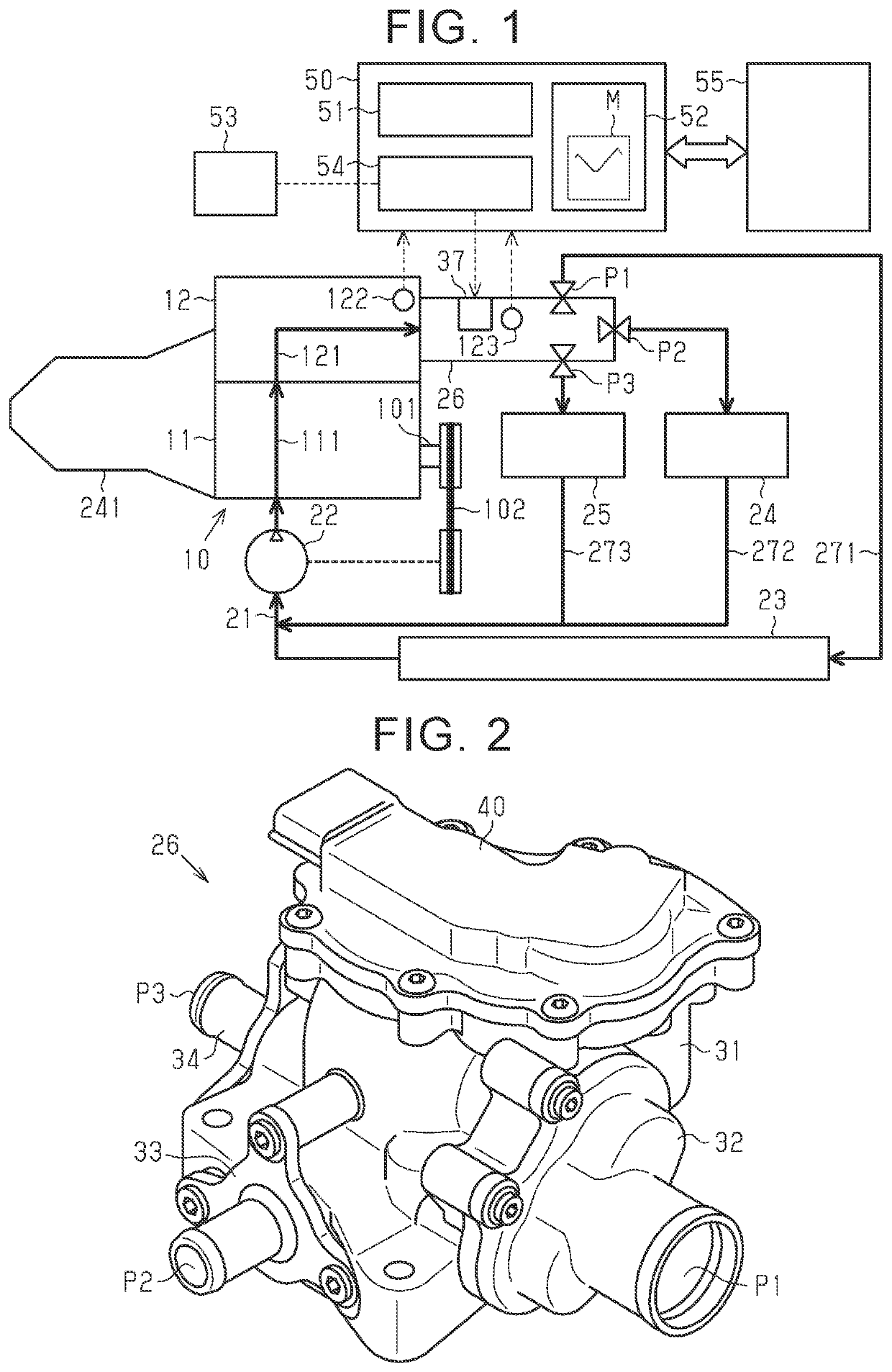
[0027]An engine cooling device according to one of the embodiments will be described hereinafter with reference to FIGS. 1 to 8. The engine cooling device according to the present embodiment is applied to an engine mounted on a vehicle having an automatic transmission. As shown in FIG. 1, the engine cooling device according to the present embodiment is equipped with a circulation circuit 21 through which coolant flowing through a water jacket 111 in a cylinder block 11 of an engine 10 and a water jacket 121 in a cylinder head 12 of the engine 10 circulates. The circulation circuit 21 is provided with a mechanical water pump 22 that discharges coolant toward the water jacket 111 in the cylinder block 11. Besides, the circulation circuit 21 is provided with three heat exchangers, namely, a radiator 23, an ATF warmer 24, and a heater core 25 of an air-conditioner for the vehicle. The radiator 23 cools coolant through the exchange of heat with outside air. The ATF warmer 24 heats up or ...


PUM


Abstract

An engine cooling device has a mechanical water pump, a flow rate control valve having a valve body of which a relative rotational position is changed by a motor, and a control unit that performs drive control of the motor to change the relative rotational position of the valve body to a target relative rotational position. The control unit performs protection control for setting the relative rotational position where a withstanding pressure limit rotational speed is equal to or higher than a current engine rotational speed, as a target operating position of the valve body of the flow rate control valve when the engine rotational speed rises, and performs retreat control for reducing a set range of the target relative rotational position to a prescribed retreat operation range when the supply voltage of the in-vehicle electric power supply has dropped.

Description

CROSS-REFERENCE TO RELATED APPLICATION[0001]This application claims priority to Japanese Patent Application No. 2019-170211 filed on Sep. 19, 2019, incorporated herein by reference in its entirety.BACKGROUND1. Technical Field[0002]The present disclosure relates to an engine cooling device that is equipped with a mechanical water pump and a flow rate control valve.2. Description of Related Art[0003]A device described in Japanese Patent Application Publication No. 2013-234605 (JP 2013-234605 A) is conventionally known as a water-cooling engine cooling device that cools an engine by circulating coolant through a water jacket formed inside the engine. The engine cooling device described in Japanese Patent Application Publication No. 2013-234605 (JP 2013-234605 A) is equipped with a mechanical water pump that delivers coolant to a water jacket in response to rotation of an engine, and an electronic control valve that closes to limit the outflow of coolant from the water jacket. Moreover,...

Claims


Application Information

Patent Timeline
IPC IPC(8): F01P5/12F02F1/16F01P7/14
CPCF01P5/12F02F1/16F01P2025/08F01P2007/146F01P2025/64F01P7/14F01P3/20F01P5/10F01P3/02F01P2003/028F01P2060/045F01P2060/08F01P2025/33F01P7/165
Inventor TAKAGI, NOBORUKATO, KAZUKIYAMAGUCHI, MASAAKITAKAOKA, TOSHIO
Owner TOYOTA JIDOSHA KK
Features
  • Generate Ideas
  • Intellectual Property
  • Life Sciences
  • Materials
  • Tech Scout
  • Unparalleled Data Quality
  • Higher Quality Content
  • 60% Fewer Hallucinations
Learn More