Dual-row cable structure

Active Publication Date: 2021-03-25
ADVANCED CONNECTEK INC
View PDF0 Cites 3 Cited by
  • Summary
  • Abstract
  • Description
  • Claims
  • Application Information

AI Technical Summary

Benefits of technology

The patent describes a dual-row cable structure that has advantages such as reduced cost and space requirement, easier processing, reduced interference between signals, and improved EMI / RFI issues. The structure consists of two rows of cables or wiring harnesses separated by a distance, with high-speed signal wires sharing the same wire diameter as power wires and low-speed signal wires. The wires are processed in two times, reducing difficulties and defect rates. The spacing between each pair of high-speed signals is increased, reducing interference and the need for ground wires. The EMI / RFI problem is improved by applying a metallic covering member and a shielding member. The overall goal is to provide a compact and efficient cable structure with improved performance and reliability for thin-and-short consumer electronic products.

Problems solved by technology

Consumer electronics tend to become smaller, thinner, and lighter.
For an electronic device (e.g., a notebook computer), the size of the electronic device is small, and the electronic device has a relatively limited internal space.
The first problem is the larger width and space needed by the flat cable structure.
As a result, the flat cable structure does not meet the thin-and-short design trend for the nowadays consumer electronic products.
The second problem is the difficulties in processing the flat cable structure.
Moreover, for these wires, the materials of the insulation layers and the sizes of the core wires are different, thereby making the difficulties in the pealing and welding processes.
Furthermore, the defect rate and the processing time for the product may be increased.
The third problem is the interference between the high-speed signals.
As a result, the signals of the adjacent high-speed signal pairs may be interfered with each other to cause improper crosstalk (for example, in the case that the flat cable structure has 42 AWG wires, the distance between adjacent wires may be too close).
The fourth problem is the electromagnetic interference (EMI) / radiofrequency interference (RFI) issue.
As a result, when the flat cable structure is used for high-speed signal transmissions, EMI / RFI problems may occur easily.

Method used


Image

  • Dual-row cable structure
  • Dual-row cable structure
  • Dual-row cable structure

Examples


Embodiment Construction

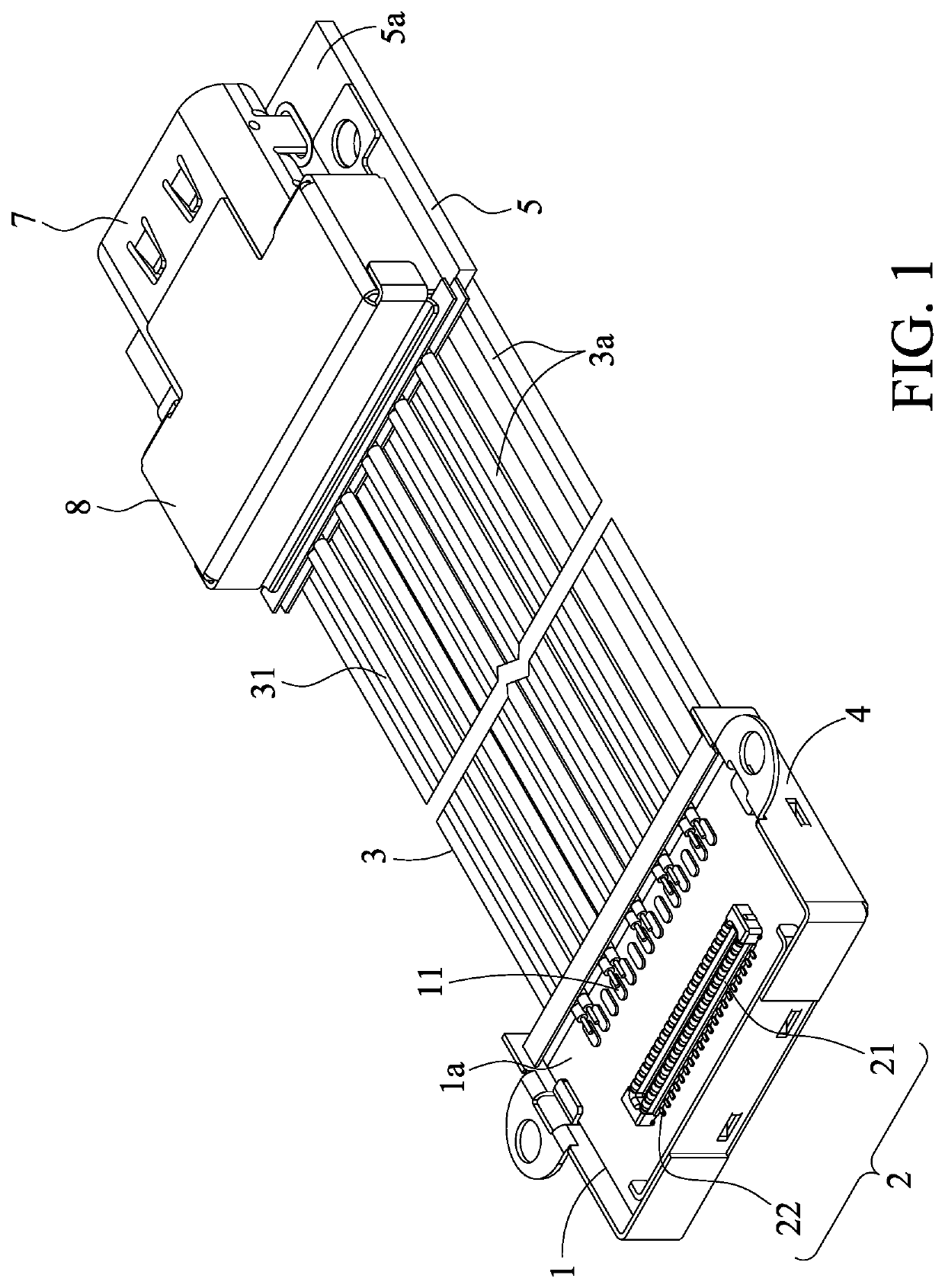
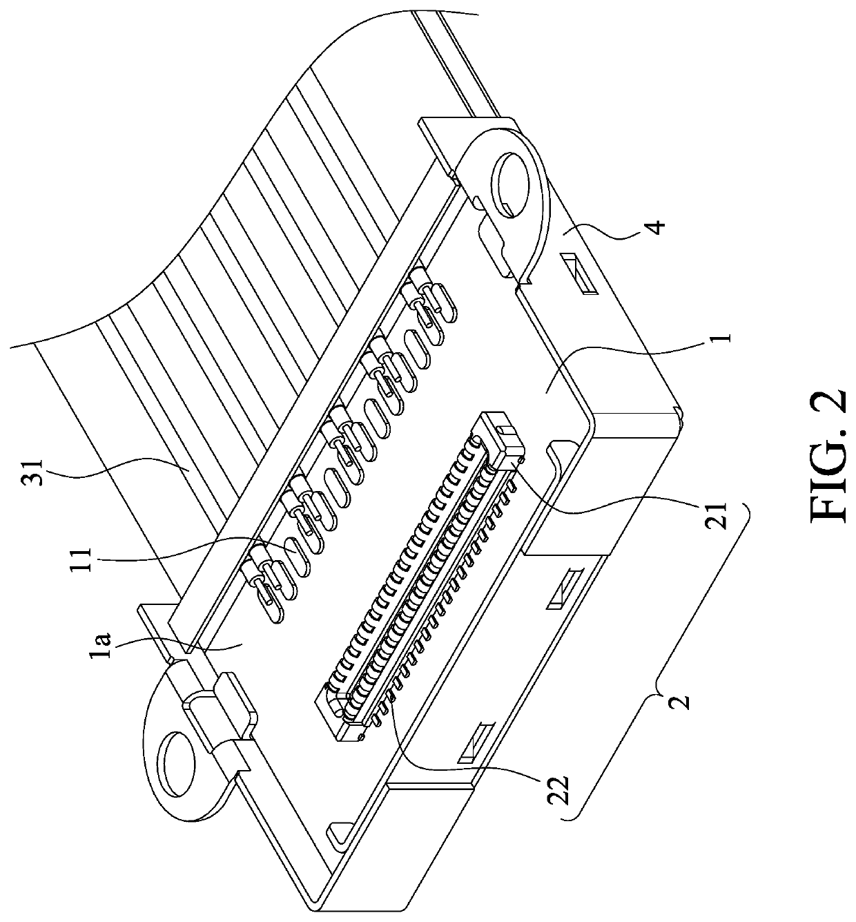
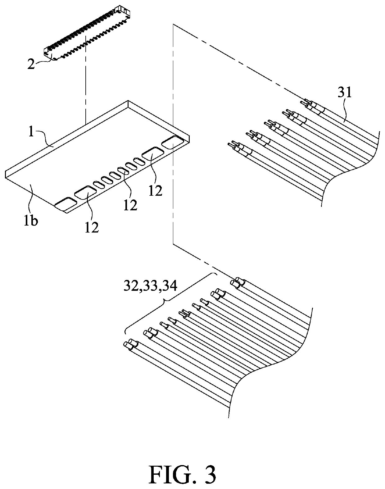
[0047]Please refer to FIGS. 1 to 6. A dual-row cable structure according to a first embodiment of the instant disclosure is illustrated. FIG. 1 illustrates a perspective view of a dual-row cable structure according to the first embodiment. FIG. 2 illustrates a perspective view of a first circuit board 1 of the dual-row cable structure of the first embodiment. FIG. 3 illustrates a partial exploded view showing the first circuit board 1, a board-to-board connector 2, and a wire assembly 3 of the dual-row cable structure of the first embodiment. FIG. 4 illustrates a perspective view of a second circuit board 5 of the dual-row cable structure of the first embodiment. FIG. 5 illustrates a partial front exploded view showing the second circuit board 5, a USB type-C connector 7, and the wire assembly 3 of the dual-row cable structure of the first embodiment. FIG. 6 illustrates a partial back exploded view showing the second circuit board 5, the USB-type C connector 7, and the wire assembly...


PUM


Abstract

A dual-row cable structure is applied to a first circuit board and a second circuit board. A board-to-board connector is on the first circuit board, and the first circuit board includes a first group of contacts and a second group of contacts. An electrical connector is on the second circuit board. The second circuit board includes a third group of contacts and a fourth group of contacts. The dual-row cable structure includes a wire assembly including high-speed signal wires, low-speed signal wires, one or more power wires, and one or more ground wires. The high-speed signal wires are connected to the first group of contacts. The low-speed signal wires, the power wire, and the ground wire are respectively connected to the second group of contacts. The third group of contacts and the fourth group of contacts are respectively connected to the other end of the wire assembly.

Description

CROSS-REFERENCE TO RELATED APPLICATION[0001]This non-provisional application claims priority under 35 U.S.C. § 119(a) to Patent Application No. 201910910623.5 filed in China, P.R.C. on Sep. 25, 2019, the entire contents of which are hereby incorporated by reference.FIELD OF THE INVENTION[0002]The instant disclosure relates to a cable structure, and more particular to a dual-row cable structure.BACKGROUND[0003]Consumer electronics tend to become smaller, thinner, and lighter. The electrical connection between the circuit boards with wires is a common configuration in the consumer electronics. Hence, the layout of the first circuit board can be extended through the wires, so that the internal space of the consumer electronics can be properly arranged. For an electronic device (e.g., a notebook computer), the size of the electronic device is small, and the electronic device has a relatively limited internal space. Therefore, the circuit boards are electrically connected with each other...

Claims


Application Information

Patent Timeline
IPC IPC(8): H01R12/71H01R24/60
CPCH01R12/716H01R2107/00H01R24/60H01R12/73H05K1/117H01R12/725H01R12/53H01R12/62H01R2201/06H01R12/712H01R13/658
Inventor WANG, WEN-YULI, JI-ZHOUCHANG, MING-YUNGLI, TZU-HAO
Owner ADVANCED CONNECTEK INC
Why Eureka
Try Eureka