
LED luminance control circuit, LED luminance control method, and LED luminance control program

Active Publication Date: 2021-03-25
EIZO
View PDF0 Cites 2 Cited by
  • Summary
  • Abstract
  • Description
  • Claims
  • Application Information

AI Technical Summary

Benefits of technology

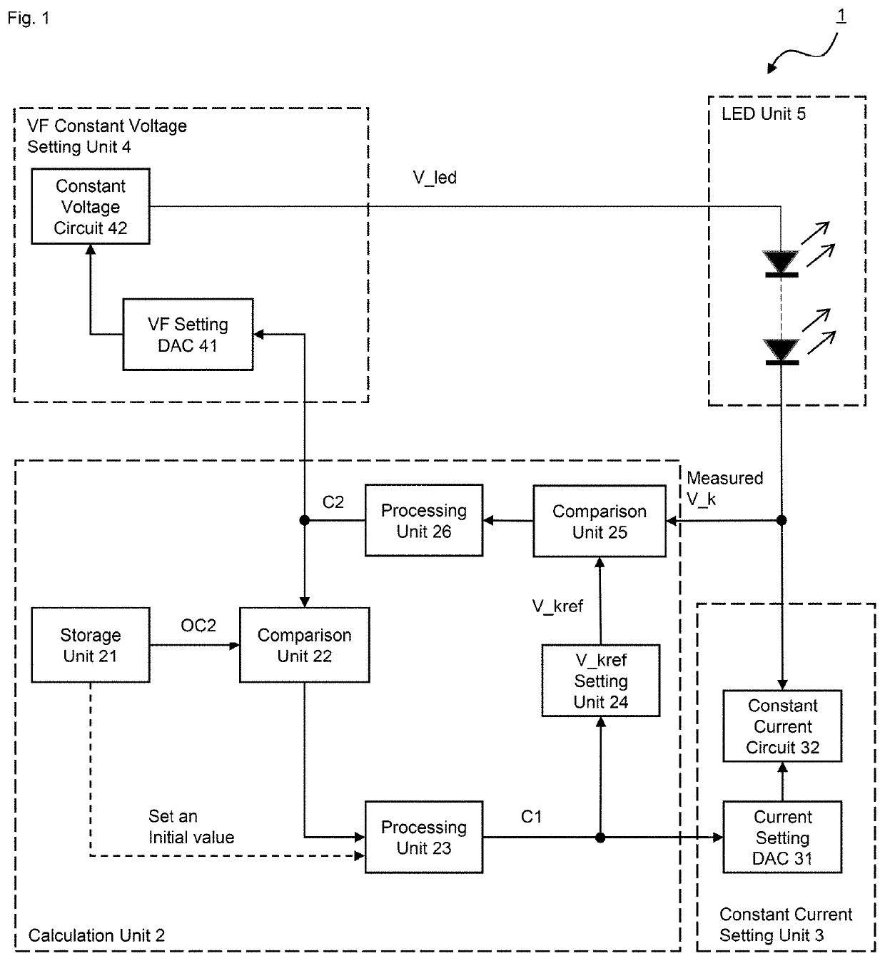
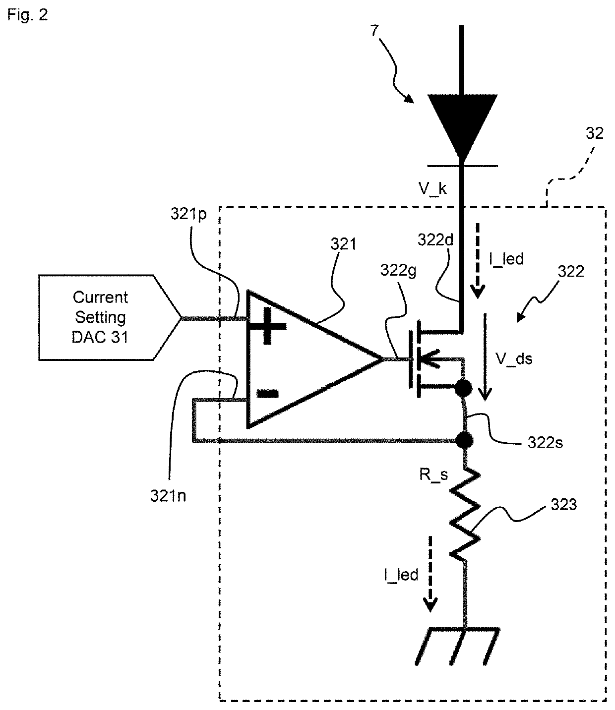
The present invention provides an LED luminance control circuit, method, and program that can stabilize the luminance of the LED while suppressing both cost and installation space. The circuit controls the value of current flowing through the LED by controlling the voltage applied to it from a power supply. This allows for early stabilization of LED luminance without the need for a temperature sensor or compensation circuit. The technical effects of the invention include reduced costs, space, and improved LED luminance stability.

Problems solved by technology

This is recognized as a significant problem particularly in medical displays and the like, in the case where stability of luminance is important.
However, in these methods, a temperature sensor or a detection circuit, and a compensation circuit are additionally required.
Thus, not only it takes much cost, but also it may be even impossible to install them due to space constraints.

Method used


Image

  • LED luminance control circuit, LED luminance control method, and LED luminance control program
  • LED luminance control circuit, LED luminance control method, and LED luminance control program
  • LED luminance control circuit, LED luminance control method, and LED luminance control program

Examples


Embodiment Construction

[0024]Hereinafter, embodiments of the present invention will be described in detail with reference to the drawings. In particular, in the present specification, a “unit” includes, for example, a combination of hardware resources implemented by a circuit in a broad sense and information process by software which can be specifically realized by these hardware resources. Further, in the present embodiment, various kinds of information are handled, but all this information is represented as a bit group of binary numbers composed of 0 or 1 by the level of the signal value, and communication or operation is performed on a circuit in a broad sense.

[0025]The circuit in a broad sense is realized by appropriately combining at least a circuit, a circuitry, a processor, a memory, and the like. That is, an application-specific integrated circuit (ASIC), a programmable logic device (for example, a simple programmable logic device (SPLD), a complex programmable logic device (SPLD), a field program...


PUM


Abstract

Provided is an ambient temperature estimating device, ambient temperature estimating method, program, and system that are able to realize both high robustness and high ambient temperature estimation accuracy. An ambient temperature estimating device includes a neural network, a temperature acquisition unit configured to acquire one or more temperature values inside the ambient temperature estimating device, and a neural network calculator configured to estimate an ambient temperature around the ambient temperature estimating device using the neural network. Input values inputted to the neural network by the neural network calculator include the temperature values acquired by the temperature acquisition unit and a heat source control value for controlling a heat source inside the ambient temperature estimating device.

Description

TECHNICAL FIELD[0001]The present invention relates to an LED luminance control circuit, an LED luminance control method, and an LED luminance control program.BACKGROUND ART[0002]Light emitting diodes (LED) are used in various fields such as lighting equipment and display devices. The LED has a polarity like other general diodes, and is used by applying a positive voltage to the anode with respect to the cathode. While the voltage is low, the current does not increase even if the voltage increases, and no light is emitted. Then, when the voltage exceeds a certain value, the increase in the current with respect to the voltage becomes rapid, and light is emitted according to the amount of current. This voltage is called a forward drop voltage (hereinafter referred to as VF).CITATION LISTPatent Literature[0003]Patent Literature 1: Japanese Patent Application No. 2008-004707SUMMARY OF INVENTIONTechnical Problem[0004]By the way, since the luminous efficiency of the LED has temperature dep...

Claims


Application Information

Patent Timeline
IPC IPC(8): H05B45/34H05B45/345H05B45/10
CPCH05B45/34H05B45/10H05B45/345G05F1/561H05B47/10
Inventor KANAYAMA, MASUMIKAWAMURA, KUNIO
Owner EIZO
Learn More