Catheter tube and method for manufacturing the same

a technology for catheters and tubes, applied in catheters, coatings, etc., can solve the problems of difficult suppression of unstable yield, etc., and achieve the effect of improving yield, safe structure, and suppressing manufacturing time and manufacturing cos

Pending Publication Date: 2021-09-30
HIRAKAWA HEWTECH
View PDF1 Cites 0 Cited by
  • Summary
  • Abstract
  • Description
  • Claims
  • Application Information

AI Technical Summary

Benefits of technology

[0031]According to the present invention, since there is no tip-side terminal of the reinforcing wire member at the tip of the catheter tube, a safe structure can be obtained, the manufacturing time and manufacturing cost can be suppressed, and the yield can be increased.

Problems solved by technology

Therefore, in the structure of the catheter tube described above, it becomes difficult to suppress the manufacturing time and manufacturing cost.
Further, when the chemical removal treatment or the like is not sufficient, the yield will not be stable.

Method used


Image

  • Catheter tube and method for manufacturing the same
  • Catheter tube and method for manufacturing the same
  • Catheter tube and method for manufacturing the same

Examples


example 1

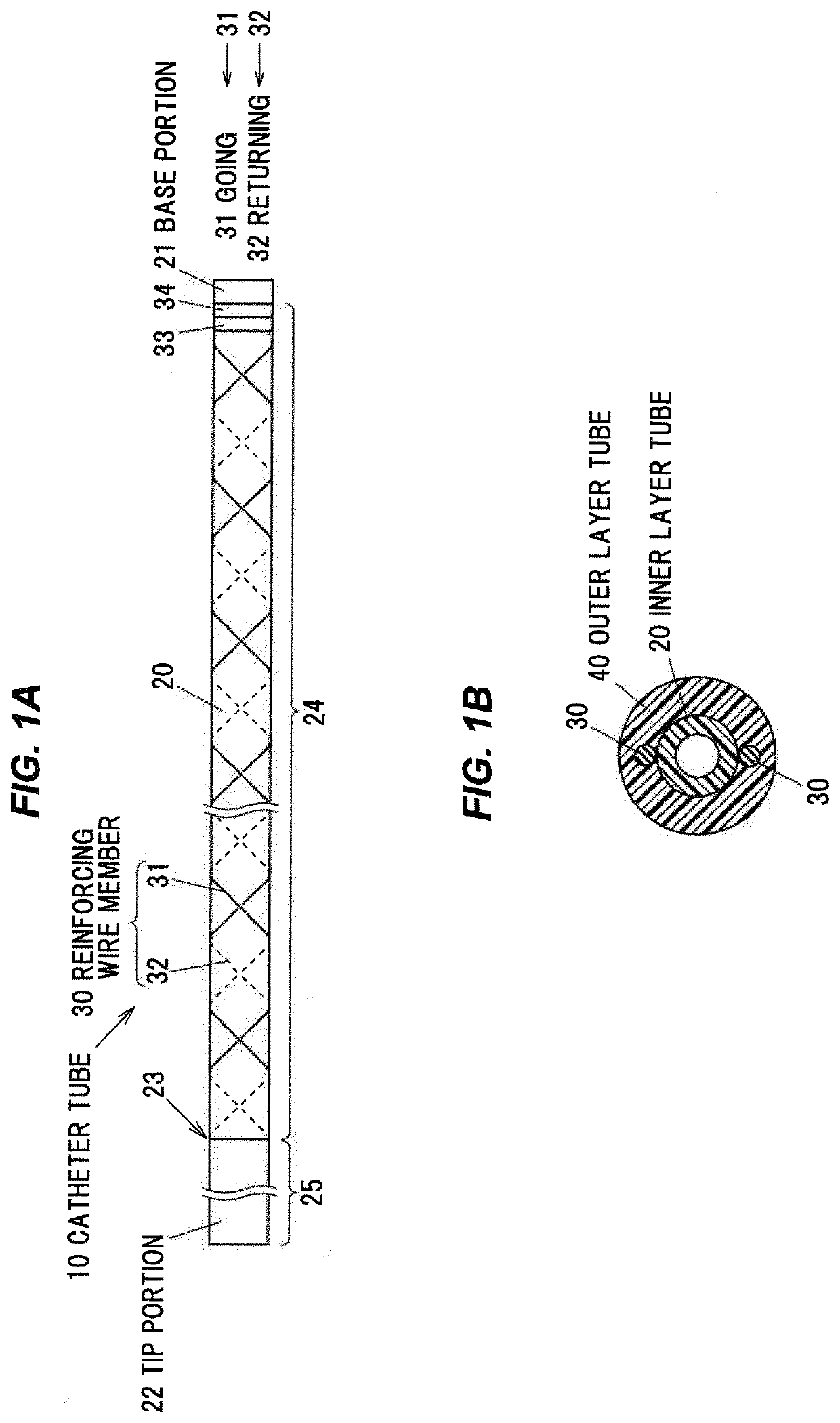
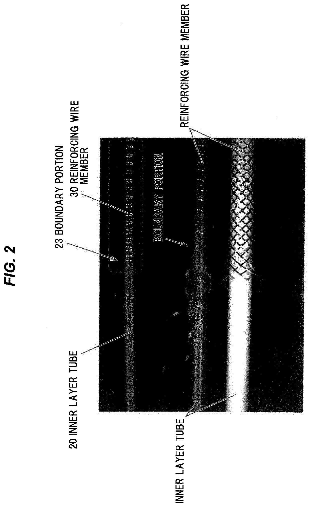
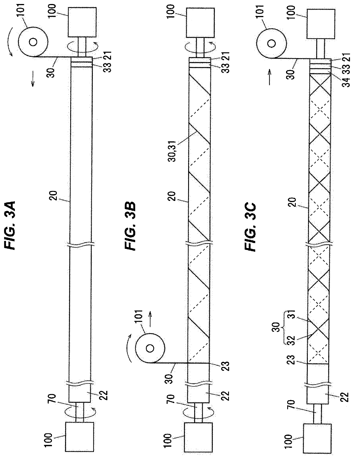
[0087]In FIGS. 5, 6A, and 6B, an outer circumference of a silver-plated soft copper core wire having a diameter of 0.43 mm was coated with fluororesin (PTFE) to provide the inner layer tube 20 with a thickness of 0.02 mm, and the inner layer tube 20 was subjected to chemical etching treatment. After fixing two reinforcing wire members 30 made of SUS304WPB and each having a wire diameter of 0.25 mm to the first adhesive portion 33 at an interval of 180 degrees, the reinforcing wire members 30 were wound around the inner layer tube 20 at reinforcing wire member moving speed of 9.6 mm / min and reinforcing wire member winding rate of 80 RPM (winding pitch of 0.12 mm, reinforcing wire member density of 37.30%) for 1800 mm Thereafter, the moving direction of the reinforcing wire members 30 was switched to an opposite direction, and the reinforcing wire members 30 were wound back to the starting position of the winding, and the winding ends of the reinforcing wire members 30 were adhered to...

example 2

[0090]In FIGS. 5, 6A, and 6B, an outer circumference of a silver-plated soft copper core wire having a diameter of 1.07 mm was coated with 12 nylon resin to provide the inner layer tube 20 with a thickness of 0.07 mm After fixing two reinforcing wire members 30 made of SUS304W1 and each having a wire diameter of 0.03 mm to the first adhesive portion 33 to be aligned in parallel with each other, the reinforcing wire members 30 were wound around the inner layer tube 20 at inner layer tube moving speed of 40 mm / min, reinforcing wire member carrier rotation rate of 80 RPM (winding pitch of 0.5 mm, reinforcing wire member density of 11.70%) for 1800 mm Thereafter, the moving direction of the reinforcing wire members 30 was switched to an opposite direction, and the reinforcing wire members 30 were wound back to the starting position of the winding, and the winding ends of the reinforcing wire members 30 were adhered to the second adhesive portion 34.

[0091]By fixing the reinforcing wire m...


PUM

PropertyMeasurementUnit
thicknessaaaaaaaaaa
diameteraaaaaaaaaa
diameteraaaaaaaaaa

Abstract

A catheter tube includes an inner layer tube as an axial center portion, a reinforcing wire member composed of a first helical portion helically wound around the inner layer tube from a base portion of the inner layer tube to an intermediate position near a tip portion, and a second helical portion helically wound around by being folded in a direction intersecting with the first helical portion at the intermediate position, and an outer layer tube covering the inner layer tube and the reinforcing wire member.

Description

CROSS-REFERENCE TO RELATED APPLICATION[0001]The present application is based on Japanese Patent Application No. 2020-64848 filed on Mar. 31, 2020, the entire contents of which are incorporated herein by reference.BACKGROUND OF THE INVENTION1. Field of the Invention[0002]The present invention relates to a catheter tube and a method for manufacturing the same, more particularly, to the catheter tube with improved safety and the method for manufacturing the same.2. Description of the Related Art[0003]The catheter tube is a lengthy tube having a tip-side that is a side inserted into a body (blood vessels, etc.) and a hand-side for performing handling, operation or the like. Such a catheter tube has a laminated structure in which an inner layer tube, a reinforcing layer provided on the inner layer tube, and an outer layer tube are integrated.[0004]In such a catheter tube, at a tip-side end of the reinforcing layer, a tip-side terminal of a reinforcing wire member is provided as a part of...

Claims


Application Information

Patent Timeline
Patent Type & Authority Applications(United States)
IPC IPC(8): A61M25/00
CPCA61M25/0053A61M25/0045A61M25/0009A61M25/0012A61M25/005A61M25/0052
Inventor SAKAMOTO, SHO
Owner HIRAKAWA HEWTECH
Why Eureka
Try Eureka