Thermal image recording apparatus

a technology of thermal image and recording apparatus, which is applied in the direction of measuring devices, instruments, printing, etc., can solve the problems of not being able to achieve excessive heating, and achieve the effect of suppressing noise and production costs

Inactive Publication Date: 2006-12-19
FUJIFILM HLDG CORP +1
View PDF3 Cites 0 Cited by
  • Summary
  • Abstract
  • Description
  • Claims
  • Application Information

AI Technical Summary

Benefits of technology

[0015]The invention has been conducted in view of the above-described circumstances. It is a first object of the invention to provide a thermal image recording apparatus in which the installation space for a decurling mechanism, the power consumption, the production cost, and the noise level can be suppressed. It is a second object of the invention to provide a thermal image recording apparatus in which decurling corresponding to a recorded image can be conducted without lowering the image quality.
[0019]In the thermal image recording apparatus, the heating unit is configured by a plate heater, and hence the space for installing the heating unit in the thermal image recording apparatus can be reduced as compared with the case of a heating roller in which a heater or the like must be incorporated, and which must be rotatably configured.
[0029]In the thermal image recording apparatus, cooling air blown by the cooling fan strikes the thermal recording material in the state that a physical external force due to bending is applied to the material. Therefore, the thermal recording material can be decurled in a short cooling transport distance.
[0031]In the thermal image recording apparatus, the inclination angle for bending the thermal recording material is set in accordance with the amount of applied heat due to the image data, and the decurling process is conducted while bending the thermal recording material so as to attain the set inclination angle. Therefore, the thermal recording material during the cooling process is bent at an adequate angle corresponding to the image data, so that the decurling process can be surely conducted.
[0032]In the thermal image recording apparatus of the present invention, the heating unit for reheating the rear face of the thermal recording material is disposed downstream from the thermal head in the transport direction, and the correcting and cooling unit for cooling the reheated thermal recording material while causing the rear face to be concaved is disposed. Therefore, the thermal recording material which is softened in the vicinity of the glass transition temperature is cooled while being bent in the direction opposite to the curl direction, so that heating, physical correction due to application of an external force, and cooling for maintaining the corrected state are sequentially applied to the thermal recording material which is kept to be in a usual transported state. Consequently, it is not required to dispose a heat roller having a large diameter, and a mechanism for inverting the thermal recording material, with the result that the installation space, the power consumption, the production cost, and the noise level can be suppressed.
[0033]Moreover, the bending degree in the decurling process of cooling the thermal recording material while bending the material in a direction opposite to the curl direction is adjusted in accordance with the quantity of heat which is given to the material in order to conduct image recording. Therefore, the decurling process can be adequately conducted in accordance with the image data.

Problems solved by technology

Since the thermal recording material is cooled and subjected to the decurling process while being bent in the direction opposite to the curl direction, the excessive heating is not requested.

Method used


Image

  • Thermal image recording apparatus
  • Thermal image recording apparatus
  • Thermal image recording apparatus

Examples


first embodiment

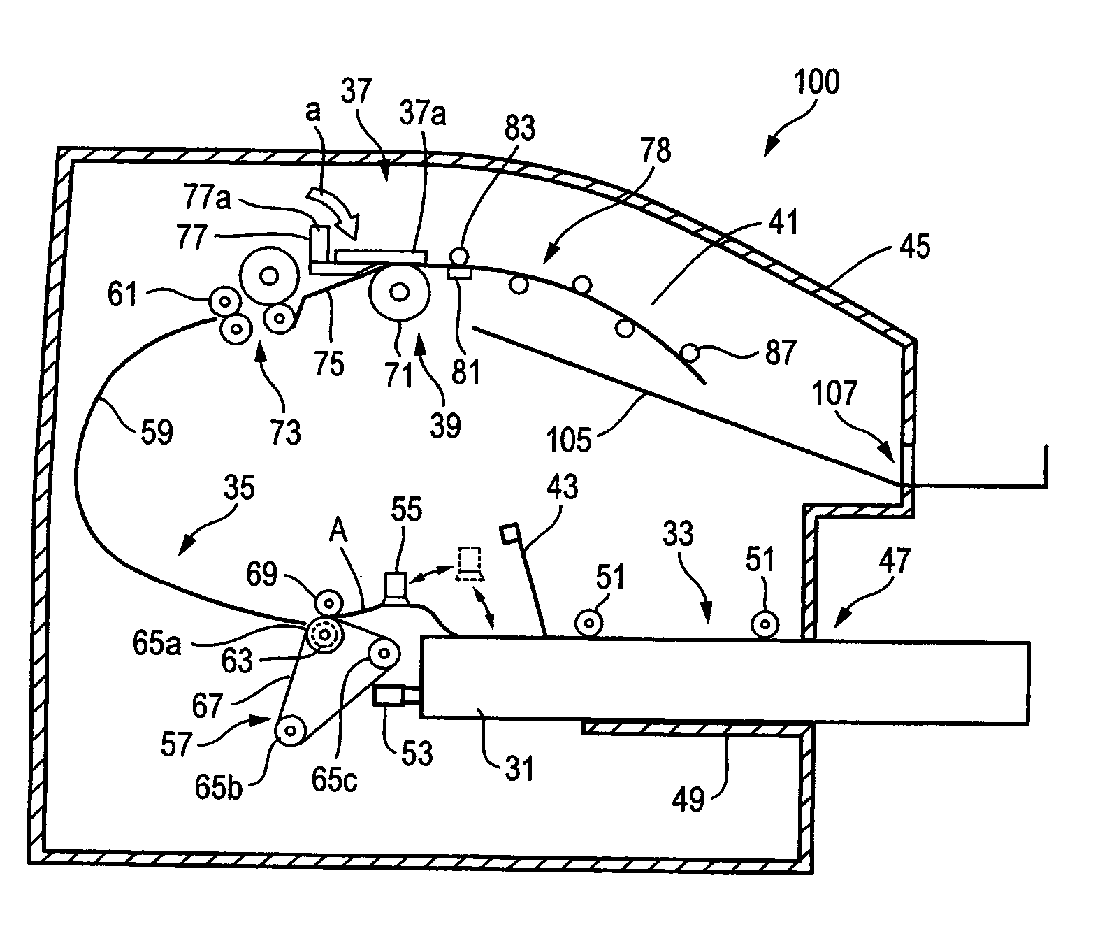
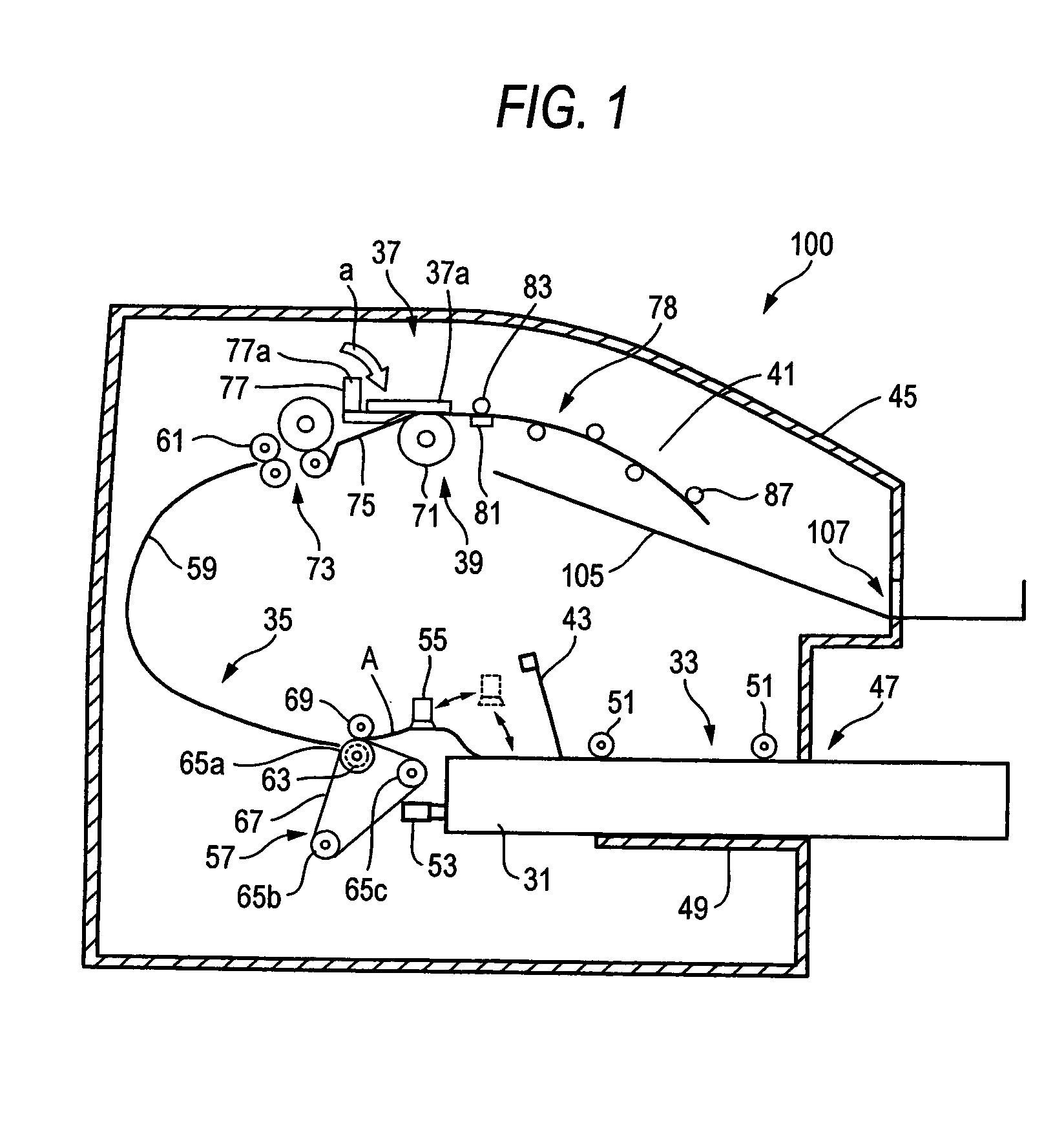
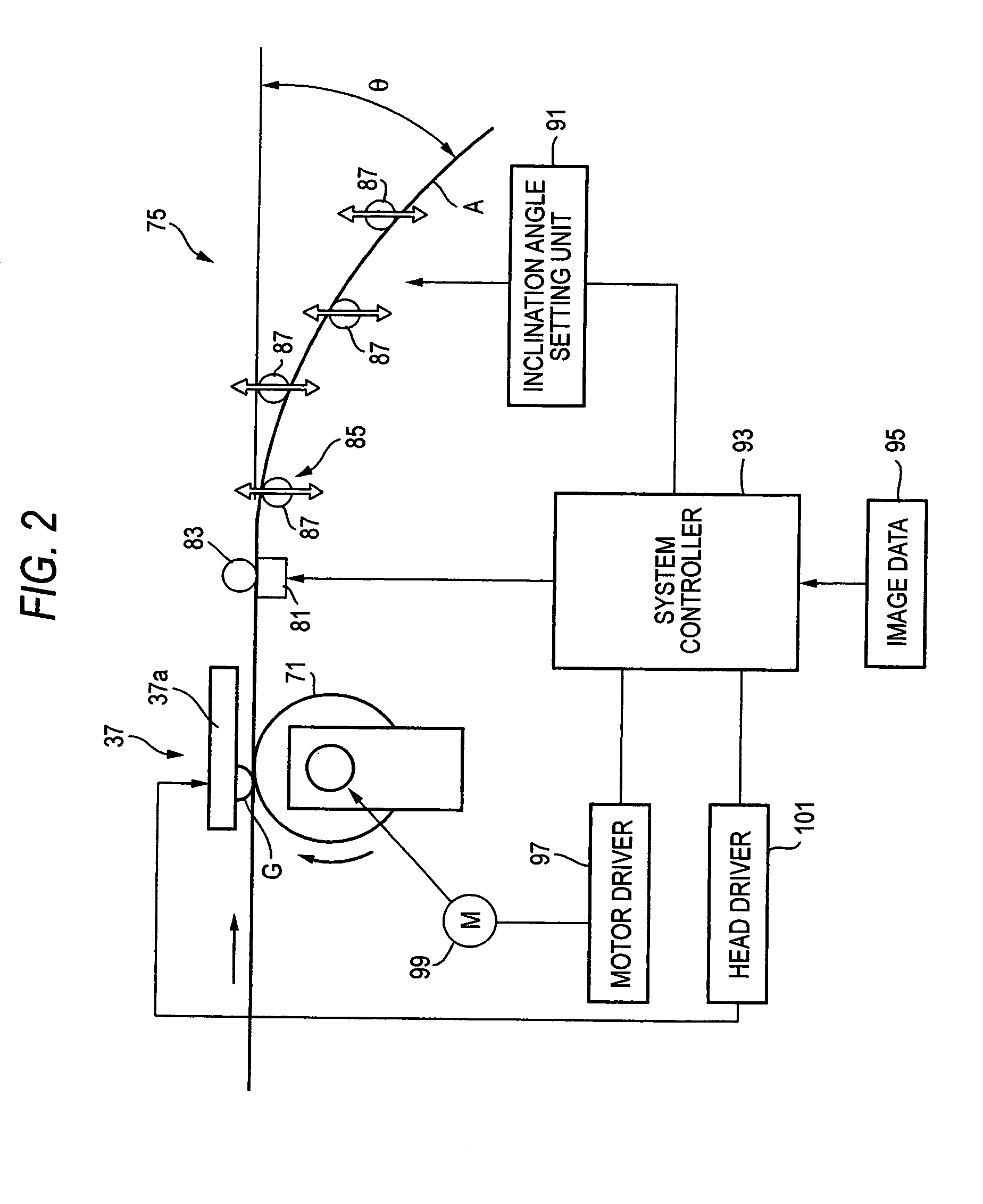
[0042]FIG. 1 is a diagram showing the whole of the thermal image recording apparatus of the invention, and FIG. 2 is a diagram showing main portions of heating unit and correcting and cooling unit of the thermal image recording apparatus of FIG. 1.

[0043]A thermal image recording apparatus 100 (hereinafter, often referred to also as the recording apparatus 100) conducts thermal image recording on a thermal recording material (hereinafter, referred to as a thermal film) A which is a cut sheet of a predetermined size such as size B4. The recording apparatus has: a loading section 33 into which a magazine 31 accommodating thermal films A is to be loaded; a feeding / transporting section 35; a recording section 39 in which a thermal head 37 conducts thermal image recording on the thermal film A; and a discharging section 41.

[0044]Each of the thermal films A uses a transparent film such as polyethylene terephthalate (PET) as a support, and has a thermal recording layer which is formed by ap...

second embodiment

[0063]Next, the thermal image recording apparatus of the invention will be described.

[0064]FIG. 3 is a diagram showing main portions of the second embodiment in which a heat roller is used as the heating unit. In the following description of the embodiments, the components identical with those shown in FIGS. 1 and 2 are denoted by the same reference numerals, and their duplicated description is omitted.

[0065]In the thermal image recording apparatus, the heating unit is composed of a heat roller 111 which is to be in contact with the rear face of the thermal film A, and the press roller 83 which cooperates with the heat roller 111 to transport the thermal film A while clampingly holding the film. The heat roller 111 incorporates a heating source such as a halogen heater 111a.

[0066]In the thermal image recording apparatus, the heating unit is configured by the heat roller 111. When the heat roller 111 and the press roller 83 are rotated in synchronization with transportation of the t...

third embodiment

[0067]Next, the thermal image recording apparatus of the invention will be described.

[0068]FIG. 4 is a diagram showing main portions of the third embodiment which comprises a flexible guide plate.

[0069]In the thermal image recording apparatus, the heating unit is composed of the heat roller 111 and the press roller 83, and the correcting and cooling unit is composed of a flexible guide plate 121 which is disposed downstream from the heating unit in the transport direction and elongates along the transport direction, and in which only a tip end portion 121a in the transport direction is movable in a direction perpendicular to the face of the thermal film A. As the flexible guide plate 121, for example, a metal plate made of stainless steel can be preferably used.

[0070]In the flexible guide plate 121, the basal end is fixed to a fixation block 123, and the transport-direction tip end portion 121a which functions as a free end is coupled to the inclination angle setting unit 91 (see FI...


PUM


Abstract

A thermal image recording apparatus has: a thermal head having a glaze in which thermal recording dots are arranged in a one direction, the thermal head conducting thermal recording on a thermal recording material that is to be in contact with the glaze, and transporting the thermal recording material in a direction perpendicular to the arrangement direction of the thermal recording dots; heating unit, disposed downstream from the thermal head in the transport direction, for reheating the rear face opposite to the recording surface of the thermal recording material; and correcting and cooling unit for cooling the reheated thermal recording material while causing the rear face to be concaved.

Description

[0001]This application is based on Japanese Patent application JP 2003-319896, filed Sep. 11, 2003, the entire content of which is hereby incorporated by reference.BACKGROUND OF THE INVENTION[0002]1. Technical Field of the Invention[0003]The present invention relates to a thermal image recording apparatus for recording an image onto a thermal recording material by heating a glaze formed by an arrangement of thermal recording dots in accordance with image data.[0004]2. Description of the Related Art[0005]Recently, thermal image recording which is conducted on a thermal recording material is used for recording an ultrasonic diagnostic image. The thermal image recording has advantages such as that a wet developing process is not required, that it is easy to handle, and that it can be suitably used in image processing. In recent years, therefore, the use of the thermal image recording is not limited to recording of a small-size image such as that in ultrasonic diagnosis, and application...

Claims


Application Information

Patent Timeline
Patent Type & Authority Patents(United States)
IPC IPC(8): B41J2/315B41J2/32B41J2/375
CPCB41J2/32B41J2/375B41J2202/34
Inventor KAMA, TAKESHI
Owner FUJIFILM HLDG CORP
Why Eureka
Try Eureka