Imaging element cleaning apparatus with structure-mandated cleaning member motion control

a technology of cleaning apparatus and cleaning element, which is applied in the field of cleaning devices, can solve the problems of insufficient effectiveness, surgeons losing vision of the surgical site, and impaired exposure surface of the imaging element thereof, and achieves the effect of effective and reliabl

Active Publication Date: 2021-04-08
CLEARCAM INC
View PDF0 Cites 0 Cited by
  • Summary
  • Abstract
  • Description
  • Claims
  • Application Information

AI Technical Summary

Benefits of technology

[0007]Embodiments of the present invention are directed to providing an effective and reliable approach for allowing an exposed surface of an imaging element (e.g., a lens) of a device (e.g., an endoscope) be cleaned while the distal end portion of the device is within a concealed operational site (e.g., in vivo). More specifically, one or more embodiments of the present invention provide an apparatus for use with an endoscope utilized in one or more types of surgical procedures (e.g., endoscopic surgery, laparoscopic surgery, thoracoscopic surgery and the like), The apparatus incorporates a cleaning member (e.g., a resilient polymeric wiper, a sponge, an absorbent pad or the like) used for cleaning the exposed surface of the imaging element of the device while the imaging element is within the concealed operation site. The apparatus is preferably adapted for having the device mounted thereon but can also be can be entirely or partially integral with one or more components of the device (e.g., a robotic arm configured for carrying, operating and manipulating an endoscope).
[0009]Although such high level of dimensional precision is exhibited, both the device and the cleaning apparatus have respective manufacturing tolerances that can influence the efficiency, effectiveness and predictability by which the cleaning member cleans the imaging element. For example, in view of cleaning apparatuses configured in accordance with embodiments of the present invention relying upon contact with portions of the device comprising the imaging element (e.g., direct surface contact between the imaging element and the cleaning member), these manufacturing tolerances can influence a degree of force and / or deflection that the cleaning member exhibits as it comes into contact with the imaging element and thereby influence cleaning performance. Similarly, in some situations (e.g., rate of speed by which the cleaning member is brought into contact with the imaging element, direction of motion of the cleaning member and the like), other consideration can also influence the degree of force and / or deflection that the cleaning member exhibits as it comes into contact with the imaging element.
[0010]Advantageously, cleaning apparatuses configured in accordance with embodiments of the present invention can include a mechanism for selectively adjusting the axial position of the cleaning member—an axial position adjuster. The axial position of the cleaning member is relative to the distal end portion of the device (e.g., the distal end portion of the extension portion of the endoscope). In most instances, the axial position will be relative to a face of an imaging element exposed at an end face of the extension portion. Through such adjustment of the axial position of the cleaning member, a user can alter the degree of force and / or deflection that the cleaning member exhibits as it comes into contact with the end portion of the endoscope and / or imaging element, thereby optimizing cleaning functionality.
[0014]It is an object of one or more embodiments of the present invention to provide a camming device that synchronously controls movement of the cleaning member.
[0021]It is an object of one or more embodiments of the present invention to provide a single control mechanism that provides for multiple modes of cleaning member movement.

Problems solved by technology

During a surgical procedure using an endoscope, the exposed surface of the imaging element thereof may become impaired due to one or more in vivo scenarios.
This method, though effective, is time consuming and causes the surgeon to lose visual of the surgical site, which can be considered dangerous (e.g., risk of infection), as surgical instruments typically remain inside the body.
Although the endoscope remains inside the body, takes less time to clean and does not potentially compromise the surgical site, this method is often not sufficiently effective either due to the “cleaning” surface not providing effective cleaning performance or simply further contaminating the exposed surface of the imaging element.
Also, when using either of these cleaning methods, the surgeon must undesirably spend time relocating the surgical site after cleaning the imaging element.
At a minimum, current approaches for cleaning the exposed surface of the imaging element can be a hindrance and an annoyance for surgeons and may offer poor cleaning performance.
Additionally, the action of cleaning the exposed surface of the imaging element increases the length of time a surgical procedure takes, thereby decreasing the amount of operating room (OR) time available to the hospital.
It is also costly for hospitals, patients, and insurance companies due to wasted time, and possibly surgical complications and post-surgical infection rates.
Additionally, as patients undergo longer procedures, their time spent under anesthesia increases.
Thus, the added time associated with current commonly used approaches for cleaning the exposed surface of the imaging element is not only a hindrance, but also potentially medically and financially costly.

Method used


Image

  • Imaging element cleaning apparatus with structure-mandated cleaning member motion control
  • Imaging element cleaning apparatus with structure-mandated cleaning member motion control
  • Imaging element cleaning apparatus with structure-mandated cleaning member motion control

Examples


Embodiment Construction

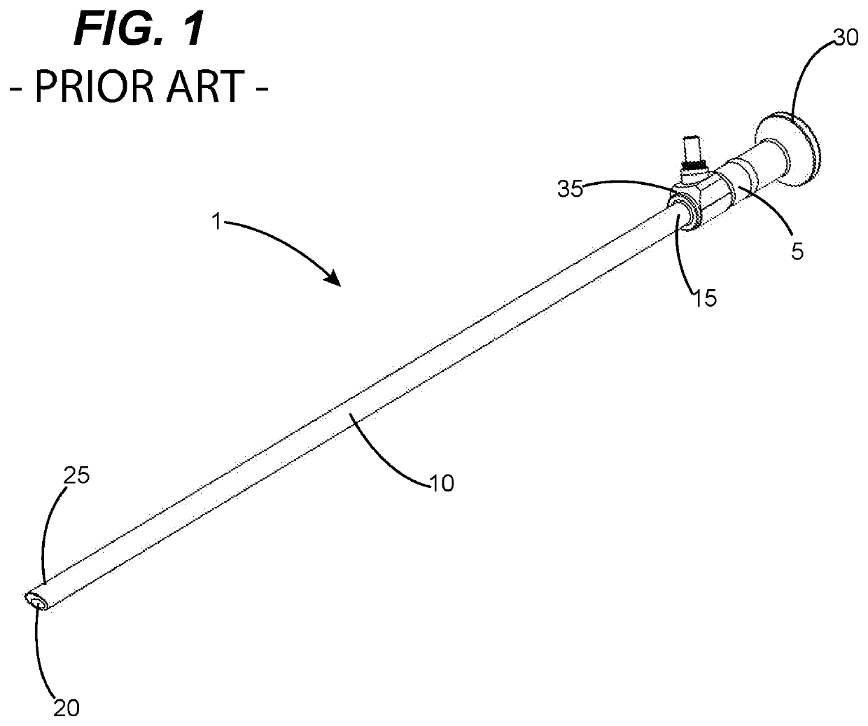
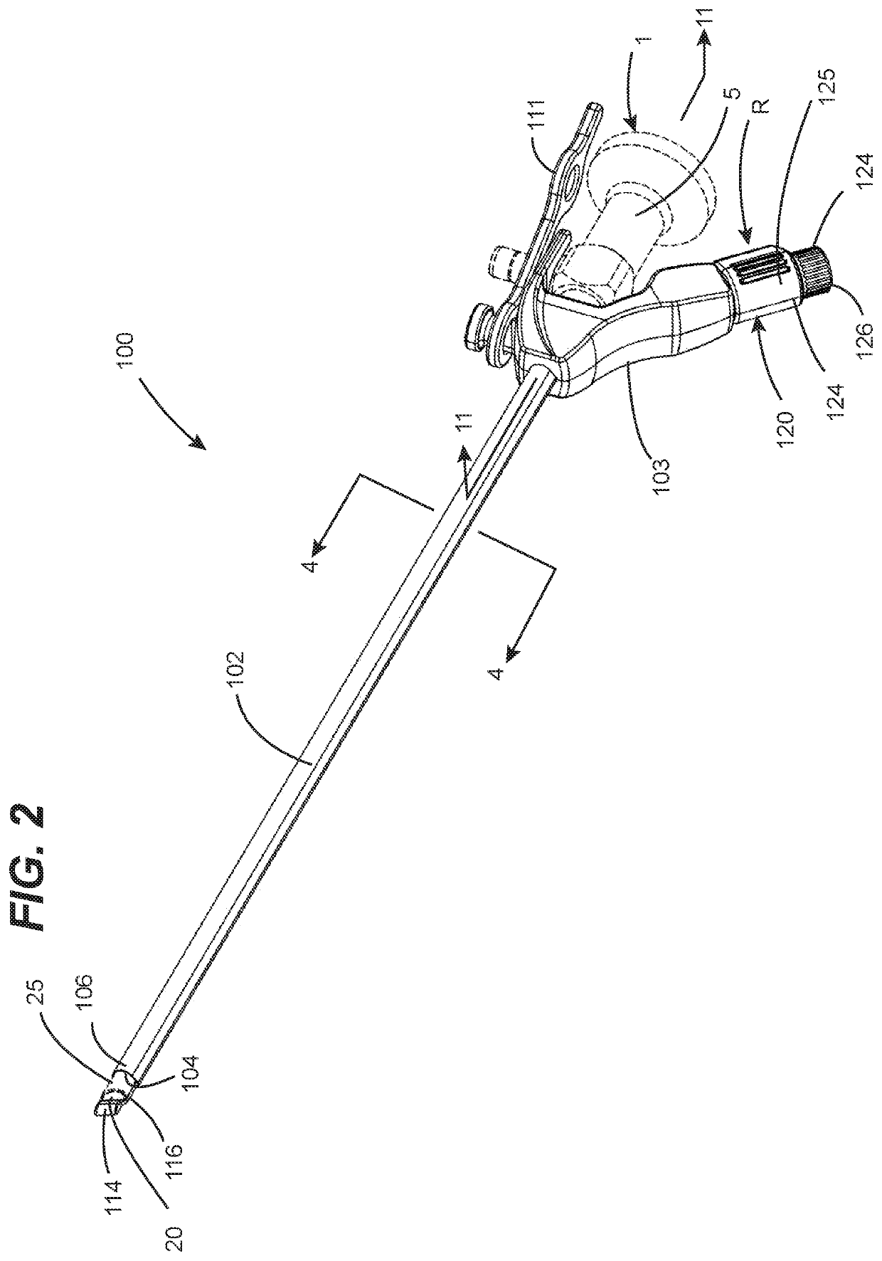
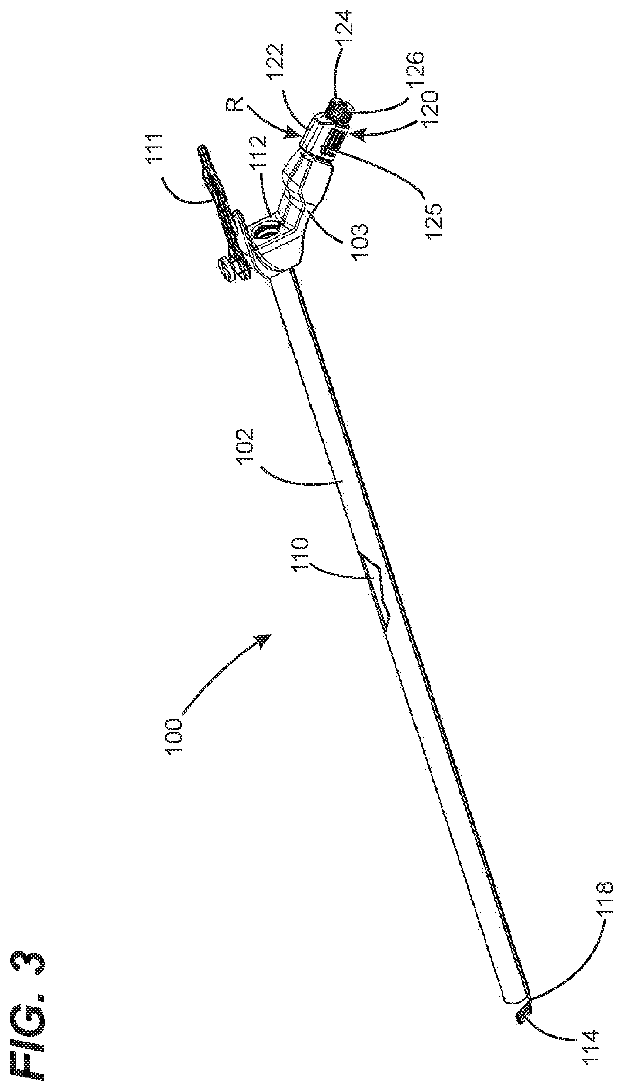
[0043]FIGS. 2-10 illustrate various aspects of an in vivo endoscope cleaning apparatus configured in accordance with a first embodiment of the present invention, which is designated as cleaning apparatus 100. Cleaning apparatus 100 is preferably, but not necessarily, configured to be used with commercially available endoscopes, such as endoscope 1 of FIG. 1. Examples of such commercially available endoscopes include, but are not limited to, endoscopes manufactured under brand names of Karl Storz, Linvatec, Olympus, Richard Wolf, Stryker and Intuitive Surgical (i.e., DaVinci). To this end, in preferred embodiments, cleaning apparatus 100 can be engineered as endoscope-specific for a given model(s) of one or more manufacturers based on the dimensional attributes of such commercially available endoscopes. An underlying consideration of the manner in which the endoscope cleaning apparatus 100 is engineered for an intended brand(s) or model(s) of endoscope is that there be a high level o...


PUM


Abstract

Embodiments of the present invention are directed to providing an effective and reliable approach for cleaning an exposed surface of an imaging element (e.g., a lens) of apparatuses including but not limited to medical imaging instruments such as endoscopes and laparoscopes and the like. In the case of medical imaging instruments, cleaning apparatuses configured in accordance with embodiments the present invention can be cleaned while the distal end portion of the endoscope is in vivo. Such apparatuses have a cleaning member incorporated therein (e.g., a resilient polymeric wiper, a sponge, an absorbent pad or the like) that is used for cleaning the exposed surface of the imaging element. The apparatus is preferably adapted for being mounted on imaging apparatus but can also be entirely or partially integral with one or more components of the imaging apparatus or system of which it is a component.

Description

FIELD OF THE DISCLOSURE[0001]The disclosures made herein relate generally to cleaning of devices that utilize a remote imaging element for visualization of structures at a concealed site and, more particularly, to an imaging element cleaning apparatus utilizing structure-mandated motion control for cleaning an exposed surface of the imaging element while the exposed surface is located within a concealed site such as an in vivo human or animal environment.BACKGROUND[0002]Surgical procedures utilizing in vivo visualization of target surgical sites are well known as a form of a concealed operation site. Examples of these surgeries include, but are not limited to, endoscopic surgery, laparoscopic surgery, thoracoscopic surgery and the like. These surgical procedures all utilize a surgical instrument having an integrated visualization device for providing in vivo visualization of a target surgical site within a surgical space of the patient. Although it is common for the surgical instrum...

Claims


Application Information

Patent Timeline
Patent Type & Authority Applications(United States)
IPC IPC(8): A61B1/12A61B1/00
CPCA61B1/126A61B1/3132A61M2209/10A61B1/00087A61B1/00135A61B1/00066A61B2090/701A61B90/70
Inventor GILKEY, JAMES LANDONGILKEY, MITCHELL ROSS
Owner CLEARCAM INC
Why Eureka
Try Eureka