

Linear-motor type transport device for transporting material for absorbent article and method for manufacturing absorbent article
- Summary
- Abstract
- Description
- Claims
- Application Information
AI Technical Summary
Benefits of technology
Problems solved by technology
Method used
Image

Examples
first embodiment
Structure of Transport Device for Transporting Material for Absorbent Article
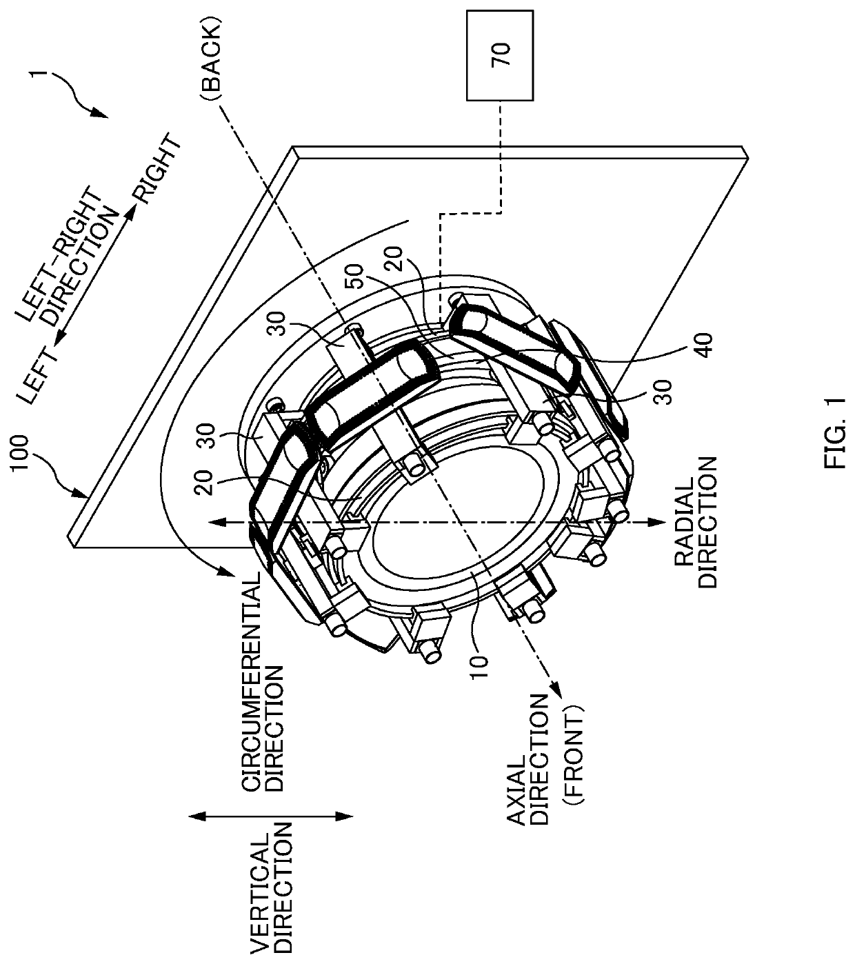
[0093]A first embodiment is described in connection with a transport device 1 for transporting material for an absorbent article (hereinafter also simply called a “transport device 1”) that transports materials (for example, an absorbent body) for absorbent articles such as diapers and napkins. FIG. 1 is a perspective view of an entire structure of the transport device 1 according to the first embodiment. The transport device 1 includes a shaft portion 10, guide portions 20, mobile units 30, a cam mechanism 40, conductors 50, and a control unit 70. The transport device 1 is fixed to a wall 100 that is erected vertically (in a vertical direction in FIG. 1) from a horizontal surface such as a ground surface or a surface plate. The transport device 1 has an axial direction, a radial direction, and a circumferential direction defined as per illustrated in FIG. 1. In the following description, with respect to th...
second embodiment
[0115]A second embodiment is described in connection with the transport device 2 in which the conductors 50 are disposed at each of two positions in the axial direction. FIG. 7 is a schematic sectional view of the transport device 2 according to the second embodiment. FIG. 7 corresponds to FIG. 4 illustrating the first embodiment.
[0116]In the transport device 2 illustrated in FIG. 7, in the axial direction, a first conductor 51 is disposed on the back side with respect to the first guide portion 21 and on the front side with respect to the wall 100, and a second conductor 52 is disposed on the front side with respect to the second guide portion 22. On the main body portion 31 of the mobile unit 30, a first magnet 36a is disposed at a position opposing the first conductor 51 in the radial direction, and a second magnet 36b is disposed at a position opposing the second conductor 52 in the radial direction. Components other than the conductor 50 and the magnet 36 are similar to those i...
third embodiment
[0119]A third embodiment is described in connection with the transport device 3 in which the conductor 50 is driven to rotate in the circumferential direction. FIG. 9A is a perspective view illustrating an entire structure of an example of the transport device 3 according to the third embodiment, and FIG. 9B illustrates a state of the transport device 3 illustrated in FIG. 9A when viewed from the upper side in a vertical direction. FIG. 10 is a schematic sectional view of the transport device 3.
[0120]In addition to the structure of the transport device 1 according to the first embodiment or the transport device 2 according to the second embodiment, the transport device 3 includes a conductor drive unit 60 for driving the conductor 50 to rotate in the circumferential direction. The conductor drive unit 60 includes a drive motor 61, a drive output pulley 62, a drive input pulley 63, and a power transmission belt 64. The drive motor 61 is fixed on the back side in the axial direction w...
PUM
 Abstract
Description
Claims
Application Information