Material transfer vehicle with modular engine assembly

a technology of material transfer vehicle and engine, applied in the direction of jet propulsion mounting, combustion air/fuel air treatment, roads, etc., can solve the problems of high cost of equipment needed to produce asphalt paving material, difficult to achieve, and large space requirements, etc., to achieve greater vehicle stability, convenient and safer access, and lower center of mass

Inactive Publication Date: 2021-04-15
ROADTEC
View PDF0 Cites 0 Cited by
  • Summary
  • Abstract
  • Description
  • Claims
  • Application Information

AI Technical Summary

Benefits of technology

The invention is a material transfer vehicle that has a lower center of mass for better stability, provides safer and more convenient access to the engine and fluid tanks, locates the engine, pump section, and cooling subassemblies away from the operator, and has a modular component design that simplifies manufacturing. The invention also uses the terms "attached," "connected," and "interconnected" to describe the relationships between structures in the vehicle. The use of the term "asphalt paving material" refers to a bituminous paving mixture used for paving purposes.

Problems solved by technology

Because the equipment needed to produce asphalt paving material is expensive and the space required extensive, asphalt paving material is typically produced in a production facility that is dedicated to such purpose.
However, such contact can be a problem when large tractor-semitrailer units are used as delivery vehicles, particularly when the truck bed is extended to its highest point.
This method of delivery requires multiple truck maneuvers that are often difficult to achieve without stopping the paving machine.
However, when a paving machine stops and subsequently restarts, its floating screed will produce a dip in the asphalt mat (when the machine stops) and a bump (when it restarts).
This may be difficult to manage when the paving machine is proceeding through intersections or operating on curved sections of the roadway.
Furthermore, the ability of the paving machine operator to place a smooth mat on the roadway will be affected by the rate of feed of asphalt paving material to the paving machine.
However delays at the production facility or traffic encountered by the delivery trucks can thwart the efforts of the most careful planners.
This may result in heat losses in the asphalt paving material in the waiting trucks, which can affect the quality of the asphalt mat being created by the paving machine.
This may also result in heat losses in the asphalt paving material in the waiting windrows, which can affect the quality of the asphalt mat being created by the paving machine.
Furthermore, in the conventional configuration, an operator cannot access the engine for maintenance, or to fill the fluid tanks, from ground level.

Method used


Image

  • Material transfer vehicle with modular engine assembly
  • Material transfer vehicle with modular engine assembly
  • Material transfer vehicle with modular engine assembly

Examples


Embodiment Construction

[0045]This description of the preferred embodiments of the invention is intended to be read in connection with the accompanying drawings, which are to be considered part of the entire written description of this invention. The drawing figures are not necessarily to scale, and certain features of the invention may be shown exaggerated in scale or in somewhat schematic form in the interest of clarity and conciseness.

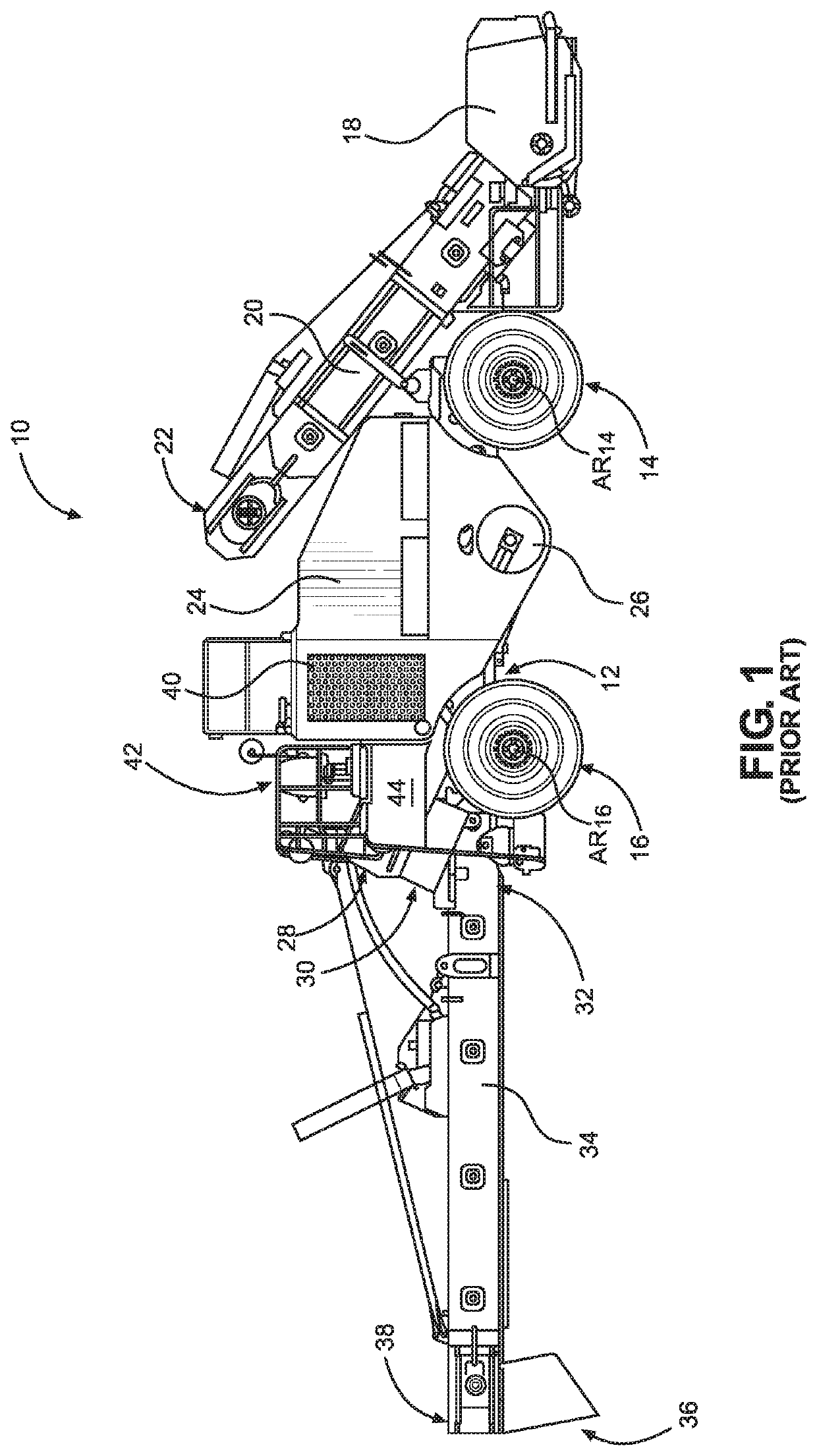
[0046]As shown in FIG. 1, a conventional self-propelled material transfer vehicle 10 includes a frame 12 that is supported on the roadway surface by front and rear ground-engaging drive assemblies including right front drive wheel 14 (which rotates about axis of rotation AR14, which is perpendicular to the page on which FIG. 1 is displayed) and right rear drive wheel 16 (which rotates about axis of rotation AR16, which is perpendicular to the page on which FIG. 1 is displayed). Material transfer vehicle 10 also includes a left front drive wheel (not shown but substantially...


PUM


Abstract

A material transfer vehicle includes a frame, a plurality of ground-engaging drive assemblies that define a plane of locomotion, a front end and a rear end. A discharge conveyor is located at the rear end and is adapted to convey asphalt paving material to the receiving hopper of an asphalt paving machine. An engine provides the motive force for driving the ground-engaging drive assemblies and is located on the frame at the rear end of the material transfer vehicle behind the ground-engaging drive assemblies and below the discharge conveyor. In a preferred embodiment of the invention, a fuel tank and a hydraulic fluid tank are located between the ground-engaging drive assemblies.

Description

CROSS-REFERENCE TO RELATED APPLICATION[0001]This application claims the benefit of U.S. Provisional Patent Application No. 62 / 913,367, which was filed on Oct. 10, 2019.FIELD OF THE INVENTION[0002]This invention relates generally to material transfer vehicles, and more particularly, to a material transfer vehicle having a physical configuration that provides greater machine stability, easier access to the engine and to the fuel and hydraulic tanks, while locating the engine away from the vehicle operator.BACKGROUND OF THE INVENTION[0003]Asphalt paving material is comprised of an asphaltic binder and aggregates of various particle sizes, including both coarse and fine aggregate materials. Because the equipment needed to produce asphalt paving material is expensive and the space required extensive, asphalt paving material is typically produced in a production facility that is dedicated to such purpose. Consequently, it is frequently necessary to transport the asphalt paving material fr...

Claims


Application Information

Patent Timeline
IPC IPC(8): B65G15/28E01C23/00B60K15/063B60K5/00F02M35/10F02M31/20F01P5/10F01N3/08F15B21/00
CPCB65G15/28E01C23/00B60K15/063B60K5/00E01C2301/04F02M31/20F01P5/10F01N3/08F15B21/00F02M35/10091B60K2015/0634B60K2015/0636B65G21/12B65G41/008E01C19/48F01N13/18F01P3/20F01P2060/02F01P2060/04F01P2060/10Y02T10/12
Inventor NEISEN, MATTHEW
Owner ROADTEC
Why Eureka
Try Eureka