

Absolute linear encoder
a technology of absolute linear encoder and encoder, which is applied in the direction of converting sensor output, measuring devices, instruments, etc., can solve the problem of not being able to provide a linear encoder having an arbitrary size and maintaining high productivity, and achieve the effect of high producibility
- Summary
- Abstract
- Description
- Claims
- Application Information
AI Technical Summary
Benefits of technology
Problems solved by technology
Method used
Image

Examples
first example embodiment
[0020][First Example Embodiment]
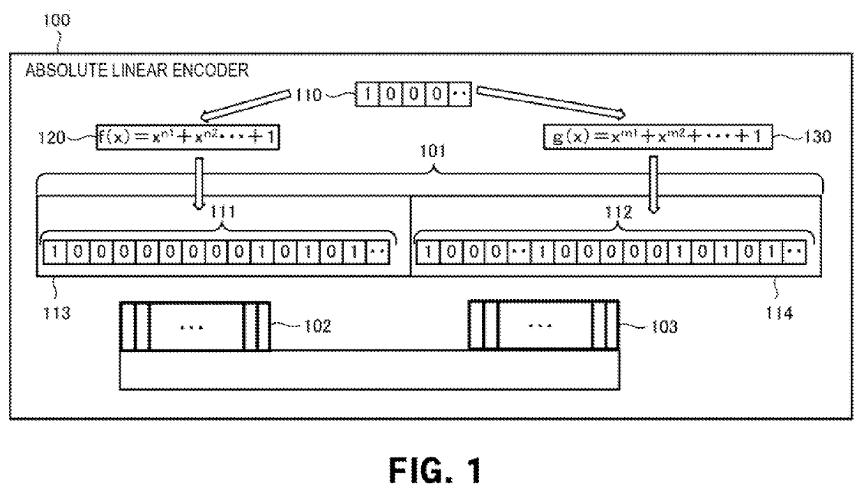
[0021]An absolute linear encoder 100 according to the First example embodiment of the present invention will be described with reference to FIG. 1. The absolute linear encoder 100 is an encoder that detects an absolute position in a linear direction. As shown in FIG. 1, the absolute linear encoder 100 includes a long scale 101, and sensors 102 and 103. The long scale 101 is formed by continuously connecting short scales 113 and 114 in which cyclic bit strings 111 and 112 generated using the same initial value 110 for different generator polynomials 120 and 130 are arranged. The at least two sensors 102 and 103 are arranged at positions facing the long scale 101 side by side in the longitudinal direction of the long scale 101. The sensors 102 and 103 are arranged at a predetermined distance and move together.
[0022]According to this example embodiment, as compared to a case in which a long scale is generated by one cyclic bit string, it is possible to i...
second example embodiment
[0023][Second Example Embodiment]
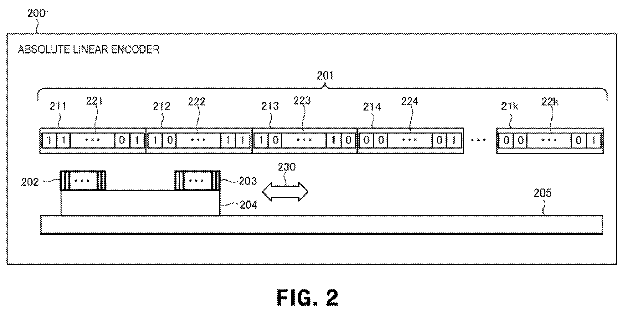
[0024]An absolute linear encoder 200 according to the second example embodiment will be described next with reference to FIGS. 2 to 5. FIG. 2 is a view for explaining the outline of the overall arrangement of the absolute linear encoder 200 according to this example embodiment. The absolute linear encoder 200 includes a long scale 201, sensors 202 and 203, a linear slider 204, and a slide rail 205.
[0025]The long scale 201 includes short scales 211, 212, 213, 214, and 21k. Cyclic bit strings 221, 222, 223, 224, and 22k are arranged in the short scales 211, 212, 213, 214, and 21k, respectively. The short scales 211, 212, 213, 214, and 21k are scales having the same length.
[0026]The cyclic bit strings 221, 222, 223, 224, and 22k are hit strings with different arrangements. That is, the cyclic bit strings 221, 222, 223, 224, and 22k are (2n−1)-bit cyclic bit strings generated using the same initial value for different generator polynomials, for example, ...
third example embodiment
[0043][Third Example Embodiment]
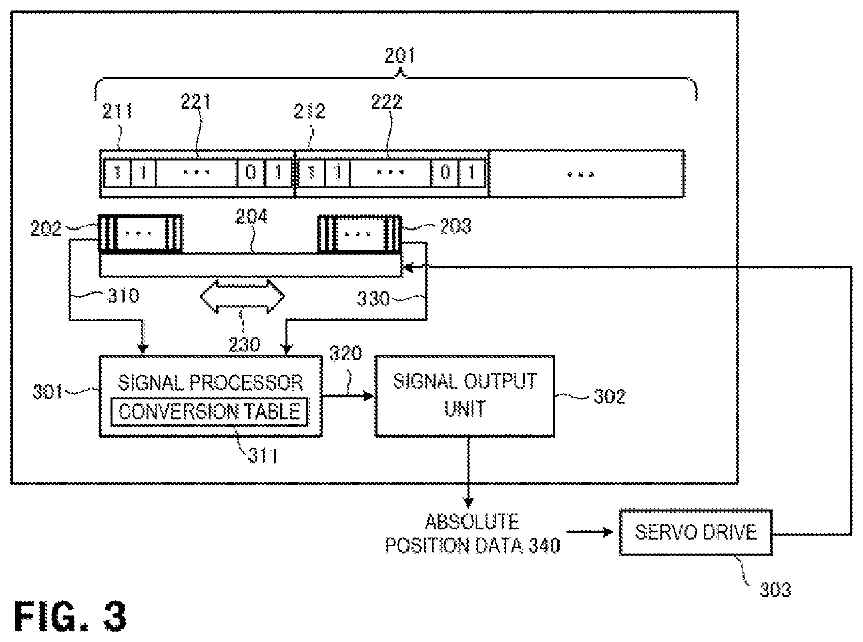
[0044]An absolute linear encoder 300 according to the third example embodiment of the present invention will be described next with reference to FIG. 5. FIG. 5 is a block diagram for explaining the outline of the overall arrangement of the absolute linear encoder 500. The absolute linear encoder 500 according to this example embodiment is different from the second example embodiment in that short scales are arranged at intervals. The rest of the components and operations is the same as in the second example embodiment Hence, the same reference numerals denote similar components and operations, and a detailed description thereof will be omitted.
[0045]The absolute linear encoder 500 includes a long scale 501. The long scale 501 includes short scales 211, 212, 213, 214, and 21k. The short scales 211, 212, 213, 214, and 21k included in the long scale 501 are arranged at intervals 511 to 51k-1.
[0046]For example, as shown in FIG. 5, if a sensor 203 detects ...
PUM
 Abstract
Description
Claims
Application Information