Container-handling vehicle

Active Publication Date: 2021-04-22
AUTOSTORE TECH AS
View PDF0 Cites 0 Cited by
  • Summary
  • Abstract
  • Description
  • Claims
  • Application Information

AI Technical Summary

Benefits of technology

The invention is a container-handling vehicle that has a brushless DC motor between its two ends. This motor reduces the length of the vehicle's lifting shaft, making it more compact and efficient. The technical effect is to minimize the space needed for the lifting shaft while maintaining its functionality.

Problems solved by technology

Having such an assembly of multiple movable parts is not an optimal solution since the lifting devices are relatively service intensive, noisy and occupies a large volume inside the robot.

Method used


Image

  • Container-handling vehicle
  • Container-handling vehicle
  • Container-handling vehicle

Examples


Embodiment Construction

[0092]In the following, embodiments of the invention will be discussed in more detail by way of example only and with reference to the appended drawings. It should be understood, however, that the drawings are not intended to limit the invention to the subject-matter depicted in the drawings.

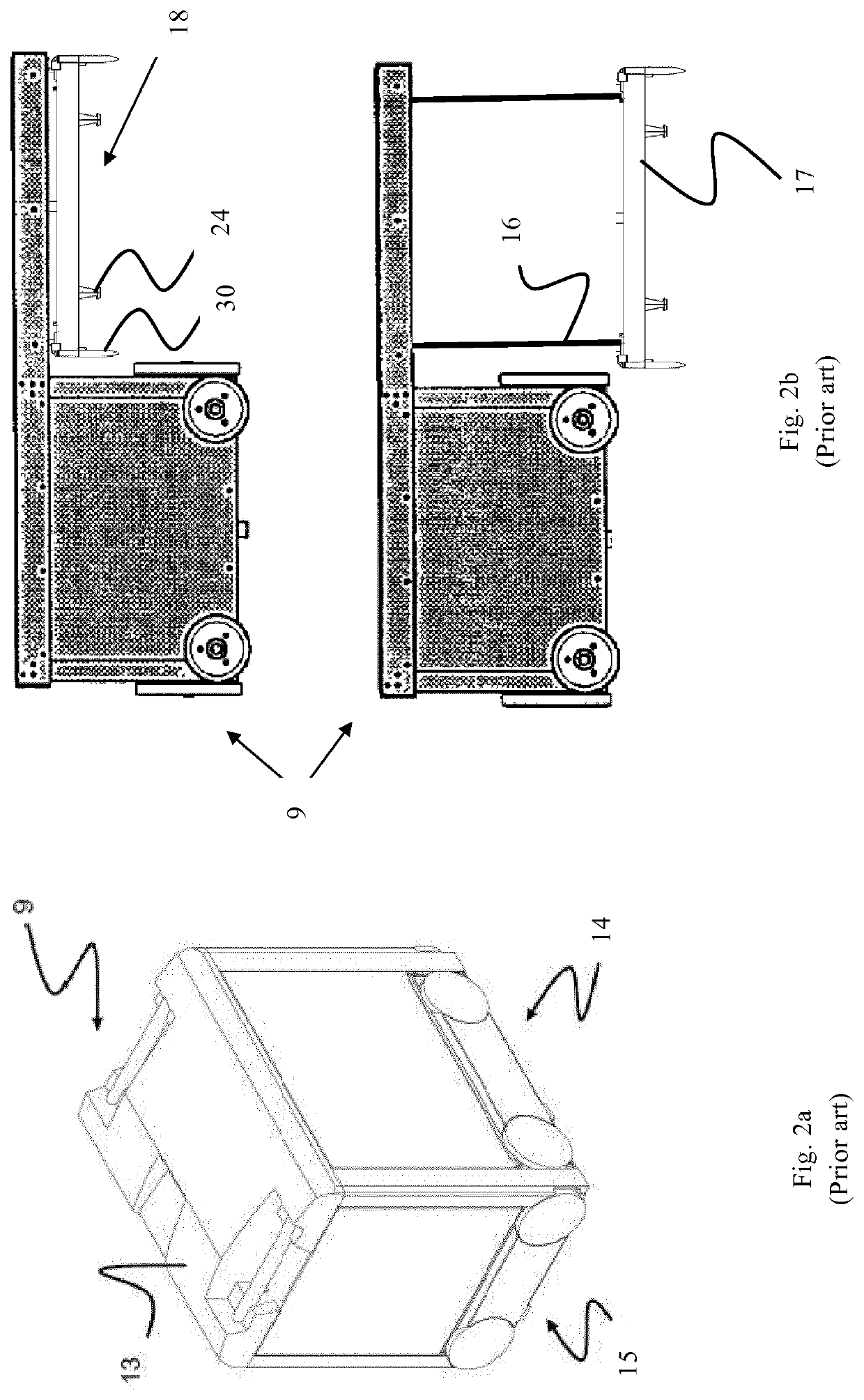
[0093]As mentioned above, a disadvantage of the prior art lifting devices 18 is the requirement of a lifting band drive assembly featuring a plurality of secondary shafts and / or sheaves, onto which the lifting bands 16 are spooled on and off, to provide the required positioning of the lifting bands relative the lifting frame.

[0094]Further, to rotate the secondary shafts and / or sheaves they are connected to a rotor shaft via belts / chains.

[0095]An exemplary embodiment of a container-handling vehicle 9′ according to the invention is shown in FIGS. 5, 6a and 6b. The main differential feature of the vehicle 9′ in view of the prior art vehicles 9, is the inventive lifting device 18′.

[0096]As described...


PUM


Abstract

The present invention provides a container-handling vehicle (9′) for picking up storage containers (6) from a three-dimensional grid (4) of an underlying storage system (1), comprising a vehicle body (13) and at least one lifting device (18′) for lifting a storage container (6) from the grid (4), the lifting device (18′) comprises a lifting band drive assembly (47, 47,31) connected to the vehicle body (13), a horizontal lifting frame (17) for releasable connection to a storage container (6), and four lifting bands (6a,16b) connecting the lifting band drive assembly (47, 47′, 31) to the lifting frame (17); the lifting band drive assembly (47, 47′, 31) comprises a lifting shaft assembly (47, 47′) having a lifting shaft (22, 22′) and at least one motor (23) for rotating the lifting shaft (22, 22′); and the lifting shaft (22) comprises a first end section (27a) and a second end section (27b); two of the lifting bands (16a,16b) are connected at each of the first and second end sections of the lifting shaft; and the lifting shaft assembly comprises at least one electrical insulating element (35, 54) arranged such that the lifting bands connected at the first end section is electrically insulated from the lifting bands connected at the second end section.

Description

TECHNICAL FIELD[0001]The present invention relates to a container handling vehicle and an automated storage and retrieval system comprising the container handling vehicle.BACKGROUND AND PRIOR ART[0002]Storage systems comprising a three-dimensional storage grid structure, within which storage containers / bins are stacked on top of each other, are well known.[0003]FIG. 1 discloses a framework structure of a typical prior art automated storage and retrieval system 1 and FIGS. 2a and 2b disclose known container-handling vehicles of such a system. The storage system is disclosed in detail in for instance NO317366 and WO 2014 / 090684 A1.[0004]The framework structure comprises a plurality of upright members / profiles 2 and a plurality of horizontal members 3, which are supported by the upright members 2. The members 2, 3 may typically be made of metal, e.g. extruded aluminium profiles.[0005]The framework structure defines a storage grid 4 comprising multiple grid columns 12 arranged in rows. ...

Claims


Application Information

Patent Timeline
IPC IPC(8): B65G1/04B66C17/06B66C13/22
CPCB65G1/0464B66C13/22B66C17/06B65G1/0492B65G1/04B66C13/14
Inventor AUSTRHEIM, TROND
Owner AUTOSTORE TECH AS
Why Eureka
Try Eureka