Check patentability & draft patents in minutes with Patsnap Eureka AI!

Layered finite element analysis of laminated composite structures

a composite element and finite element technology, applied in the field of composite structures, can solve the problems of inability to capture resin behaviour, inability to accurately predict the delamination of composite elements, and limited methods

Pending Publication Date: 2021-04-29
BELL TEXTRON RHODE ISLAND INC +1
View PDF0 Cites 0 Cited by
  • Summary
  • Abstract
  • Description
  • Claims
  • Application Information

AI Technical Summary

Benefits of technology

The patent describes a method for analyzing a composite structure using a computer-implemented method. The method involves creating a model of the composite structure by representing the plurality of plies and layers of bonding agent using two-dimensional and three-dimensional elements. The in-plane and out-of-plane properties of the composite structure are then analyzed to predict delamination. The method can be used to analyze a variety of composite structures, such as Tee-joints, bonded joints, sandwich-structured composites, angle plies, joggles, and complex 3D joints. The system includes a processing unit and computer-readable memory for storing the program instructions. The technical effect of the patent is to provide a reliable and accurate method for analyzing composite structures to predict delamination and failure under various loading conditions.

Problems solved by technology

These methods are however confined to in-plane loading conditions and do not capture the resin behaviour in the out-of-plane (or through-the-thickness) direction because perfect bonding between plies is assumed.
Hence, existing methods do not provide accurate prediction of delamination of a composite element, i.e. the separation between plies which occurs when the composite element is subjected to a force normal to the plane of the plies.
This leads to inefficient and over-conservative structural designs, which in turn results in increased costs and time to market.

Method used


Image

  • Layered finite element analysis of laminated composite structures
  • Layered finite element analysis of laminated composite structures
  • Layered finite element analysis of laminated composite structures

Examples


Embodiment Construction

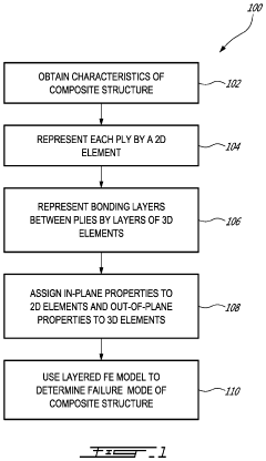
[0032]Referring now to FIG. 1, a method 100 for FE analysis of composite structures will now be described. The composite structures referred to herein are illustratively manufactured using a lamination technique where an adhesive or other bonding agent (e.g. an isotropic resin material provided in the composite structure) is used to join multiple layers (also referred to herein as ‘plies’) of high stiffness fibers together as an integral unit. In a particular composite structure, there may be numerous (e.g. tens or hundreds of) plies arranged in a stacking sequence and at least some plies may be made of differing materials. This may result in a laminated composite structure (also referred to as a ‘composite laminate’) that exhibits improved properties including, but not limited to, improve strength, stability, sound insulation, and appearance. Such composite structures may be used for a variety of applications and in a variety of industries including, but not limited to, the aerospa...


PUM


Abstract

There is provided a method and a system for finite element (FE) analysis of a composite structure comprising plies arranged according to a stacking sequence and layers of bonding agent. Each layer of bonding agent interconnects two adjacent plies. In-plane properties and out-of-plane properties of the composite structure are received. An FE model of the composite structure is generated by representing the plies by two-dimensional (2D) elements configured to be arranged according to the stacking sequence, representing the layers of bonding agent by three-dimensional (3D) elements, each 3D element configured to interconnect two adjacent 2D elements, and associating the in-plane properties with the 2D elements and the out-of-plane properties with the 3D elements. An FE analysis of the FE model is performed to predict delamination of the composite structure.

Description

TECHNICAL FIELD[0001]The present disclosure relates generally to composite structures, and more specifically to finite element (FE) modeling and analysis of laminated composite structures.BACKGROUND OF THE ART[0002]Virtual simulation of structural behavior using numerical methods, such as advanced FE simulation methods, drives cost reduction in design, testing, certification and facilitates reduction in weight and time to market, particularly in the aerospace industry.[0003]A number of FE modeling and analysis methods currently exist for composite structures, which generally consist of a matrix (or resin) that binds high stiffness fibers together as an integral unit. One such method is to model each fiber layer (or ply) in a laminate (or stack of plies) individually layer by layer, following a sequence. Plies are represented by three-dimensional brick-like FE layers attached at nodes. Another method is to model the laminate using a simplified plate-like representation. All the plies...

Claims


Application Information

Patent Timeline
IPC IPC(8): G06F17/50
CPCG06F17/5018G06F2217/16
Inventor BLANC, OLIVIERVISWESWARAIAH, SWAROOP BYLAHALLY
Owner BELL TEXTRON RHODE ISLAND INC
Features
  • R&D
  • Intellectual Property
  • Life Sciences
  • Materials
  • Tech Scout
  • Unparalleled Data Quality
  • Higher Quality Content
  • 60% Fewer Hallucinations
Learn More